Moebius-style post-processing and other stylized shaders
March 26, 2024 / 33 min read
Last Updated: March 26, 2024Physically Based Rendering (PBR) is often the defacto stylistic choice for 3D developers as tools/frameworks, for the most part, optimize for realistic materials, shadows, and lighting out-of-the-box. However, in an industry constantly pushing for realism, adopting Non-Photorealistic Rendering (NPR) or stylized shaders while still following physical principles can really make your project stand out.
There's been a recent resurgence in distinct artistic directions through the use of stylized shaders in many games. At least since Zelda BOTW came out, it's becoming more prevalent. While Hi-Fi Rush or the Persona series are great examples of Non-Photorealistic Rendering, there are a few indie games out there (e.g. Sable and Synergy) doing wonders by emulating a flavor of a hand-drawn art style which I particularly enjoy from legendary artist Jean Giraud aka Moebius.
So far, I've only ever tried reproducing physically accurate lighting effects or base my scene in the "real world" with no styling at all, and I wanted to see whether reproducing some aspect of Jean Giraud's visual art in a WebGL environment was possible. Luckily, @UselessGameDev made a great video on reproducing the Moebius style. In it, he deconstructs the key characteristics that make the Moebius style so unique and rebuilds each of them in Unity. After carefully studying the subjects covered in that video and spending a couple of days heads-down on the problem, I managed to build what is to me a very satisfying Moebius post-processing pass on top of a React Three Fiber scene. It features not only all the elements of Moebius' style (outlines, crosshatched shadows, and specular) but also elements usually featured in his more sci-fi-focused comic books: desert, spaceships, and alien planets looming in the distance.
In this article, we will deconstruct this art style and reproduce it step-by-step as a post-processing pass that you can put on top of any React Three Fiber scene. We will learn how to output hand-drawn looking outlines by leveraging an edge detection filter and stylize our final render while preserving physical elements like lighting and shadows with an extra touch of creativity. Finally, we'll look at some of the shortcomings of this render pipeline and how I worked around them in my own creations.
Setting up the stage for post-processing
We want to apply the Moebius style to a React Three Fiber scene as a whole, not just as a material of the individual meshes that compose it. Knowing that, we'll need to use a post-processing pass that can apply this style to an already rendered scene.
A post-processing pass acts like an "image filter" on top of your scene to apply any modifications you'd like. @react-three/postprocessing has many effects like Bloom, Vignette, or Depth of Field built in,
which you can find on many popular 3D websites. However, none of the prebuilt ones are even close to what we want to achieve, so we'll have to build it ourselves by implementing our own Pass based on a custom shader.
Unfortunately @react-three/postprocessing does not allow for custom passes, so we'll need to go "vanilla" and use more Three.js flavored code for this part. You may be familiar with how Three.js projects set up their post-processing pipeline
using effectcomposer and the many flags that we need to turn on for each pass to take effect, but thanks to @react-three/drei's Effects component, this entire setup is now a bit simpler:
Our scene and a skeleton post-processing pass
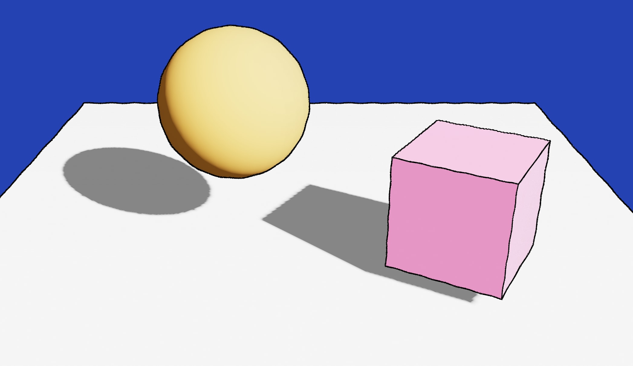
1import { Effects } from '@react-three/drei';2import { extend } from '@react-three/fiber';3import { useRef } from 'react';4import { Pass } from 'postprocessing';5import * as THREE from 'three';67class MoebiusPass extends Pass {8constructor(args) {9super();10}1112dispose() {}1314render(renderer, writeBuffer, readBuffer) {}15}1617extend({ MoebiusPass });1819const MoebiusScene = () => {20const mesh = useRef();21const ground = useRef();2223const lightPosition = [10, 10, 10];2425return (26<>27<directionalLight28castShadow29position={lightPosition}30intensity={4.5}31color="#fff"32target={ground.current}33/>34<mesh castShadow receiveShadow position={[-1, 2, 1]}>35<sphereGeometry args={[1, 32, 32]} />36<meshStandardMaterial color="orange" />37</mesh>38<mesh39castShadow40receiveShadow41rotation={[0, Math.PI / 3, 0]}42position={[2, 0.75, 2]}43>44<boxGeometry args={[1.5, 1.5, 1.5]} />45<meshStandardMaterial color="hotpink" />46</mesh>47<mesh48ref={ground}49receiveShadow50rotation={[-Math.PI / 2, 0, 0]}51position={[0, 0, 0]}52>53<planeGeometry args={[10, 10, 100, 100]} />54<meshStandardMaterial color="white" />55</mesh>56<Effects>57<moebiusPass />58</Effects>59</>60);61};6263// ...
You can see in the code snippet above that:
- We created a
MoebiusPassclass that extends fromPass. This class will let us define everything we need for our Moebius style. - We "extended" React Three Fiber's namespace with our
MoebiusPassallowing us to use it as a standard JSX component. - Finally, we used our newly created pass inside the
Effectscomponent.
Now that we wired this together, let's create a custom shader for our post-processing pass to render on the screen. We'll first create a very simple shader to make sure that everything functions as intended:
Sample post-processing pass using a custom shader material
1//...2import { FullScreenQuad } from "three-stdlib";34const moebiusShader = {5uniforms: {6tDiffuse: { value: null },7},8vertexShader: \`9varying vec2 vUv;1011void main() {12vUv = uv;1314gl_Position = projectionMatrix * modelViewMatrix * vec4(position, 1.0);15}16\`,17fragmentShader: \`18varying vec2 vUv;19uniform sampler2D tDiffuse;2021void main() {22vec2 uv = vUv;23vec4 color = texture2D(tDiffuse, uv);2425gl_FragColor = vec4(color.r + 0.2, color.g, color.b, color.a);26}27\`,28}2930class MoebiusPass extends Pass {31constructor(args) {32super();3334this.material = new THREE.ShaderMaterial(moebiusShader);35this.fsQuad = new FullScreenQuad(this.material);36}3738dispose() {39this.material.dispose();40this.fsQuad.dispose();41}4243render(renderer, writeBuffer, readBuffer) {44this.material.uniforms.tDiffuse.value = readBuffer.texture;4546if (this.renderToScreen) {47renderer.setRenderTarget(null);48this.fsQuad.render(renderer);49} else {50renderer.setRenderTarget(writeBuffer);51if (this.clear) renderer.clear();52this.fsQuad.render(renderer);53}54}55}56//...
Much like I explored last year in my blog post on render targets, our pass consists of a simple FullScreenQuad that overlays
the scene and a material that takes the underlying scene as a texture (tDiffuse), and modifies it. In this case, you should see that our base scene has now a red tint, as we increased the intensity of the red
channel in the fragment shader of our post-processing pass.
Drawing outlines with shaders for our React Three Fiber scene
With our post-processing pass now implemented, we can start making our way toward building some of the key aspects of the Moebius style. One of the first striking elements of this art style is its consistent outlines, as most of Jean Giraud's creations are drawings. Thus, we will need to find a way to draw outlines around all the objects of our React Three Fiber scenes and to do that, we'll need to implement an edge detection filter.
An edge detection filter identifies points in our scene where the brightness changes sharply, for instance, between the pixels of an object in the foreground and the background, to then place our outline around each object pretty accurately. In our case:
- We'll implement a Sobel Filter, a type of edge detection filter.
- We'll feed our filter both the Depth data and Normal data of our scene and combine the result obtained.
Getting the Depth Buffer of our scene
Why would we need the "depth data" of our scene? This data will tell us on which plane the objects of our scene belong and thus find any "depth discontinuities" and highlight where the outer outlines of the overall scene should be.
First things first, let's work our way towards getting the depth information of our scene. We can use our good ol' useFBO hook to create a render target, but this time, we will also pass a depthTexture onto it and flip the depthBuffer option to `true.
Setting up our depthTexture
1const depthTexture = new THREE.DepthTexture(2window.innerWidth,3window.innerHeight4);56const depthRenderTarget = useFBO(window.innerWidth, window.innerHeight, {7depthTexture,8depthBuffer: true,9});
We then use our render target within our useFrame hook to render the current scene onto it and pass its resulting depthTexture to our post-processing pass.
Passing the Depth data of the scene to our post-processing pass
1const MoebiusScene = () => {2//...3const { camera } = useThree();45useFrame((state) => {6const { gl, scene, camera } = state;78gl.setRenderTarget(depthRenderTarget);9gl.render(scene, camera);1011gl.setRenderTarget(null);12});1314return (15<>16{/*...*/}17<Effects>18<moebiusPass19args={[20{21depthRenderTarget,22camera,23},24]}25/>26</Effects>27</>28);29};
We can now try to visualize our depth texture by rendering it through the fragment shader of our custom post-processing pass. However, we'll first need to know how to "read" this texture within our fragment shader, as this is not your typical sampler2D
data that you can read with texture2D in GLSL. Luckily, @mattdesl provided a great example on how to read depth textures in one example
that he built for the Three.js documentation.
With this function, we obtain the value of the "depth" of the pixel represented by a grayscale color, which we can then return as an output of our fragment shader:
Fragment shader returning the depth of every pixel represented by a grayscale color
1#include <packing>2varying vec2 vUv;3uniform sampler2D tDiffuse;4uniform sampler2D tDepth;5uniform float cameraNear;6uniform float cameraFar;78float readDepth( sampler2D depthTexture, vec2 coord ) {9float fragCoordZ = texture2D( depthTexture, coord ).x;10float viewZ = perspectiveDepthToViewZ( fragCoordZ, cameraNear, cameraFar );11return viewZToOrthographicDepth( viewZ, cameraNear, cameraFar );12}1314void main() {15vec2 uv = vUv;1617float depth = readDepth( tDepth, vUv );1819gl_FragColor = vec4(vec3(depth), 1.0);20}
The demo below showcases the output of our post-processing pass returning the "depth data" of our scene 👇
Getting the Normal Buffer of our scene
While the depth data gives us information on the outer boundaries of our scenes, the Normal data will help us find the inner outlines within our scene:
- If our edge detection filter finds higher differences in normals, that will mean there's a very sharp corner, thus a very pronounced outline.
- If the difference in normals is not that significant, we'll get a more subtle outline or no outline under a certain threshold.
If you read my blog post on Caustics, you might be familiar with the exercise of "capturing the normals" in a render target. While this is a valid technique, it is a bit too "brute force" for our post-processing use case: we'd have to
manually apply a NormalMaterial for each mesh composing our scene 😮💨. But we don't have time for that and have better things to do! Instead, we'll override the entire scene with a NormalMaterial
(or CustomNormalMaterial in our case because we'll need to tweak it in the later parts) using the scene.overrideMaterial property:
Example of usage of the overrideMaterial property of the scene object
1scene.matrixWorldNeedsUpdate = true;2scene.overrideMaterial = NormalMaterial;
As with the depth texture, we'll define a dedicated render target for our render target, render our scene outputting its Normal data, and pass the result as an argument of our post-processing pass.
Passing the Normal data of our scene to our post-processing pass
1const MoebiusScene = () => {2const normalRenderTarget = useFBO();3//...45useFrame((state) => {6const { gl, scene, camera } = state;78gl.setRenderTarget(depthRenderTarget);9gl.render(scene, camera);1011const originalSceneMaterial = scene.overrideMaterial;12gl.setRenderTarget(normalRenderTarget);1314scene.matrixWorldNeedsUpdate = true;15scene.overrideMaterial = CustomNormalMaterial;1617gl.render(scene, camera);18scene.overrideMaterial = originalSceneMaterial;1920gl.setRenderTarget(null);21});2223return (24<>25{/*...*/}26<Effects>27<moebiusPass28args={[29{30depthRenderTarget,31normalRenderTarget,32camera,33},34]}35/>36</Effects>37</>38);39};
Finally, if needed, we can visualize the Normal data by returning it as output of our custom post-processing shader pass. There are no tricks here: we can use the standard texture2D function to read the data of our "Normal texture."
Fragment shader from our post-processing pass outputting the Normal data of the scene
1varying vec2 vUv;2uniform sampler2D tNormal;34void main() {5vec2 uv = vUv;67vec3 normal = texture2D(tNormal, vUv).rgb;89gl_FragColor = vec4(normal, 1.0);10}
The resulting scene is visible below 👇 with just a few lines of code, we got the Normal data of our entire scene!
Edge detection with Sobel filters
We have all the data necessary to detect edges and draw the outlines of our scene! As stated in the introduction of this section, we'll use an edge detection filter and, more specifically, a Sobel filter for this task.
As we read the pixels of our scene in our post-processing pass, we'll use this filter to detect sharp changes in intensity (intensity here can be a difference in depth or normals). The Sobel filter is a specific filter that has a few specificities that will help us:
- It's a convolution filter: we'll perform the edge detection by sliding over each pixel a small 3x3 matrix (also known as kernel).
- The matrix itself has specific values (also known as weights) specifically set to detect differences in pixel intensity.
- Those weights are applied on the pixel itself and its neighbors.
- It has two kernels: one to detect edges along each x/y-axis.
The matrices are defined as follows:
Sx = [[-1, 0, 1], [-2, 0, 2], [-1, 0, 1]]
Sy = [[-1, -2, -1], [0, 0, 0], [1, 2, 1]]
You may ask how we're supposed to apply this matrix/kernel to our pixel. Luckily, the math involved is not too complex here, and we can visualize it easily:
- For each pixel, we'll "overlay" the center of the kernel
- We'll multiply each value of the kernel with the value of the pixel it overlays
By adding up the result of this operation, we get a gradient or "rate of change," which corresponds to the difference in intensity between pixels processed by the filter (overlayed by the matrix to keep the explanation as visual as possible). If that output is non-zero and above a certain treshold; we detected a potential edge! The widget below aims to showcase this with some simple examples:
Code-wise, this is how we can define and apply the Sobel filter in our fragment shader:
Applying the Sobel filter to our Depth data
1//...2const mat3 Sx = mat3( -1, -2, -1, 0, 0, 0, 1, 2, 1 );3const mat3 Sy = mat3( -1, 0, 1, -2, 0, 2, -1, 0, 1 );45void main() {6vec2 texel = vec2( 1.0 / resolution.x, 1.0 / resolution.y );7float outlineThickness = 3.0;8vec4 outlineColor = vec4(0.0, 0.0, 0.0, 1.0);9vec4 pixelColor = texture2D(tDiffuse, vUv);1011// Getting the value of each pixel of our kernel -> depth11 is our current pixel12float depth00 = readDepth(tDepth, vUv + outlineThickness * texel * vec2(-1, 1));13float depth01 = readDepth(tDepth, vUv + outlineThickness * texel * vec2(-1, 0));14float depth02 = readDepth(tDepth, vUv + outlineThickness * texel * vec2(-1, -1));1516float depth10 = readDepth(tDepth, vUv + outlineThickness * texel * vec2(0, -1));17float depth11 = readDepth(tDepth, vUv + outlineThickness * texel * vec2(0, 0));18float depth12 = readDepth(tDepth, vUv + outlineThickness * texel * vec2(0, 1));1920float depth20 = readDepth(tDepth, vUv + outlineThickness * texel * vec2(1, -1));21float depth21 = readDepth(tDepth, vUv + outlineThickness * texel * vec2(1, 0));22float depth22 = readDepth(tDepth, vUv + outlineThickness * texel * vec2(1, 1));2324// Calculating the output of the filter applied to each pixels of the kernel25float xSobelValue = Sx[0][0] * depth00 + Sx[1][0] * depth01 + Sx[2][0] * depth02 +26Sx[0][1] * depth10 + Sx[1][1] * depth11 + Sx[2][1] * depth12 +27Sx[0][2] * depth20 + Sx[1][2] * depth21 + Sx[2][2] * depth22;2829float ySobelValue = Sy[0][0] * depth00 + Sy[1][0] * depth01 + Sy[2][0] * depth02 +30Sy[0][1] * depth10 + Sy[1][1] * depth11 + Sy[2][1] * depth12 +31Sy[0][2] * depth20 + Sy[1][2] * depth21 + Sy[2][2] * depth22;3233// Combining both Vertical and Horizontal output to detect all edges34float gradientDepth = sqrt(pow(xSobelValue, 2.0) + pow(ySobelValue, 2.0));3536float outline = gradientDepth;3738vec4 color = mix(pixelColor, outlineColor, outline);3940gl_FragColor = color;41}
Here, we apply the Sobel filter to the depth data we acquired in the previous section. If we try to visualize the output of this post-processing pass, this is what we get:
We only see the outer outline of the scene! To get the complete set of outlines, we must apply the same Sobel filter to our Normal data and then combine its resulting gradient with the gradient we just obtained from the depth data. The code to do this is luckily not that different, albeit repetitive, so you may want to abstract it:
Applying the Sobel filter to both our Depth data and Normal data
1//...2float luma(vec3 color) {3const vec3 magic = vec3(0.2125, 0.7154, 0.0721);4return dot(magic, color);5}67void main() {8//...9// Get the grayscale output of each pixel of our kernel10float normal00 = luma(texture2D(tNormal, vUv + outlineThickness * texel * vec2(-1, -1)).rgb);11float normal01 = luma(texture2D(tNormal, vUv + outlineThickness * texel * vec2(-1, 0)).rgb);12// ... and so on1314float xSobelNormal =15Sx[0][0] * normal00 + Sx[1][0] * normal10 + Sx[2][0] * normal20 +16Sx[0][1] * normal01 + Sx[1][1] * normal11 + Sx[2][1] * normal21 +17Sx[0][2] * normal02 + Sx[1][2] * normal12 + Sx[2][2] * normal22;1819float ySobelNormal =20Sy[0][0] * normal00 + Sy[1][0] * normal10 + Sy[2][0] * normal20 +21Sy[0][1] * normal01 + Sy[1][1] * normal11 + Sy[2][1] * normal21 +22Sy[0][2] * normal02 + Sy[1][2] * normal12 + Sy[2][2] * normal22;2324float gradientNormal = sqrt(pow(xSobelNormal, 2.0) + pow(ySobelNormal, 2.0));2526float outline = gradientDepth + gradientNormal;2728vec4 color = mix(pixelColor, outlineColor, outline);2930gl_FragColor = color;31}
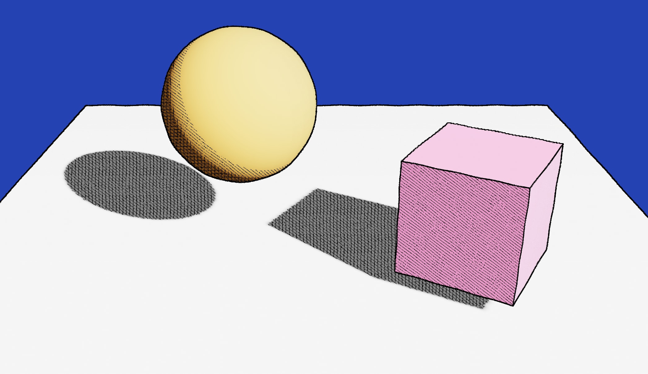
If we run the code we just implemented, our current post-processing pipeline will output our original scene, overlayed with an outline surrounding each mesh!
Stylized outlines, shadows, and lighting patterns
From the looks of the render of our scene in the previous demo, it's clear that the outlines "alone" are not enough to convey the art style of Jean Giraud. In his video, @UselessGameDev highlights a couple of specificities from the artist's technique that makes his creations so unique:
- The outlines are supposed to be hand-drawn. Ours are perfectly straight, which doesn't give that "handmade" feel.
- The shadows in Moebius' creations follow a crosshatched pattern: the darker the shadow, the denser the pattern is. Currently, our scene still renders the standard "physically based" shadows.
- The artist also usually depicts specular lighting with plain white dots surrounded an outline.
In this part, we'll examine and re-implement each of these specificities in our custom post-processing shader pass and try our hand at other stylized shaders along the way.
Giving our outlines an hand-drawn look in GLSL
We want our post-processing effect to make our scene look like a drawing, and those perfect straight outlines won't cut it. Let's make them look more wiggly by applying a slight displacement using:
- Some trigonometric functions like
sinorcos. - A wiggle factor for us to increase or decrease the frequency and amplitude of the outline.
- A
hashfunction to apply some irregularities to the outline.
1vec2 displacement = vec2(2(hash(gl_FragCoord.xy) * sin(gl_FragCoord.y * frequency)) ,3(hash(gl_FragCoord.xy) * cos(gl_FragCoord.x * frequency))4) * amplitude /resolution.xy;
We defined our displacement as a pair sinusoidal function along the x and y-axis. We made the frequency low at 0.08 as we want our outline to look like elongated waves. For the randomness, I picked up a simple hash function from this shadertoy project from markjarzynski . Now, we need to add this displacement vec2 to each depth and normal buffer pixels processed in our Sobel filter:
Adding displacement when reading the Depth and Normal data for our outlines to appear hand-drawn
1//...2float hash(vec2 p) {3vec3 p3 = fract(vec3(p.xyx) * .1031);4p3 += dot(p3, p3.yzx + 33.33);56return fract((p3.x + p3.y) * p3.z);7}89void main() {10//...11vec2 displacement = vec2(12(hash(gl_FragCoord.xy) * sin(gl_FragCoord.y * frequency)) ,13(hash(gl_FragCoord.xy) * cos(gl_FragCoord.x * frequency))14) * amplitude /resolution.xy;1516vec4 pixelColor = texture2D(tDiffuse, vUv);1718// Apply the displacement when reading the value of each pixel in the kernel19float depth00 = readDepth(tDepth, vUv + displacement + outlineThickness * texel * vec2(-1, 1));20float depth01 = readDepth(tDepth, vUv + displacement + outlineThickness * texel * vec2(-1, 0));21// and so on..2223float normal00 = luma(texture2D(tNormal, vUv + displacement + outlineThickness * texel * vec2(-1, -1)).rgb);24float normal01 = luma(texture2D(tNormal, vUv + displacement + outlineThickness * texel * vec2(-1, 0)).rgb);25// and so on...2627}
This displacement is subtle, yet it changes the entire look and feel of the scene. It now starts looking more like a drawing!


The demo below implements the displacement we just added and allows you to tweak the outline through:
- The frequency of the sinusoid functions.
- The amplitude of the wiggles.
Adding custom shadow patterns to our post-processing effect
To achieve a convincing Moebius style, we want to apply a custom shadow pattern to the shadows and the darker areas of the scene overall. That means that those patterns need to be coded within our post-processing fragment shader, where we'll need to:
- Detect whether a given pixel is part of a "dark" area.
- Color the pixel based on a given pattern.
To detect whether a pixel is part of a "dark" area of the overall scene, we can rely on the luminance of the pixel returned by the luma function we used earlier in this project to grayscale our Normal data. That is far from a bulletproof way to achieve this, but it's "good enough".
1float pixelLuma = luma(pixelColor.rgb);
With this, we can build a simple tonal shadow pattern. If the luma of a given pixel falls under a specific luma value, we change its color to a darker shade. Below is an example where:
- We declare three different thresholds under which we change the pixel color.
- Each threshold has a specific color: the lower the luma, the darker the color shade.
Custom tonal shadow pattern applied to pixels under a certain luma threshold
1//...23if(pixelLuma <= 0.35) {4pixelColor = vec4(0.0, 0.0, 0.0, 1.0);5}67if (pixelLuma <= 0.45) {8pixelColor = pixelColor * vec4(0.25, 0.25, 0.25, 1.0);9}1011if (pixelLuma <= 0.6) {12pixelColor = pixelColor * vec4(0.5, 0.5, 0.5, 1.0);13}1415if (pixelLuma <= 0.75) {16pixelColor = pixelColor * vec4(0.7, 0.7, 0.7, 1.0);17}1819//...
However, there's a catch! Our post-processing pass applies this shadow pattern to every pixel on the screen, including the background! That means that if we were to choose a background color with a low enough luminance, it would end up shaded. To solve this, we can reuse the depth buffer we introduced in the first part and use it to only apply the shadow pattern to objects that are close enough to the camera:
Making our tonal shadow pattern take into account the depth value of the pixel
1//...2float depth = readDepth(tDepth, vUv);34if(pixelLuma <= 0.35 && depth <= 0.99) {5pixelColor = vec4(0.0, 0.0, 0.0, 1.0);6}78if (pixelLuma <= 0.45 && depth <= 0.99) {9pixelColor = pixelColor * vec4(0.25, 0.25, 0.25, 1.0);10}1112if (pixelLuma <= 0.6 && depth <= 0.99) {13pixelColor = pixelColor * vec4(0.5, 0.5, 0.5, 1.0);14}1516if (pixelLuma <= 0.75 && depth <= 0.99) {17pixelColor = pixelColor * vec4(0.7, 0.7, 0.7, 1.0);18}19//...
That gives us a first simple custom shadow pattern we can use as a foundation to build more complex ones in the next part!
Crosshatched and raster shadow patterns
We'll define our Moebius shadow following what @UselessGameDev established it in his video:
- The lightest shadow will have diagonal stripes.
- The second threshold will add vertical stripes.
- Finally, the darkest shadows will have an extra set of horizontal stripes.
To draw the stripes, we can use GLSL's modulo function mod that lets us color pixels at a regular interval. For instance:
Crosshatched shadow pattern implemented by drawing stripes at given luma threshold
1//...2float modVal = 8.0;34if (pixelLuma <= 0.35 && depth <= 0.99) {5if (mod((vUv.y + displacement.y) * resolution.y , modVal) < 1.0) {6pixelColor = outlineColor;7};8}9if (pixelLuma <= 0.55 && depth <= 0.99) {10if (mod((vUv.x + displacement.x) * resolution.x , modVal) < 1.0) {11pixelColor = outlineColor;12};1314}15if (pixelLuma <= 0.80 && depth <= 0.99) {16if (mod((vUv.x + displacement.x) * resolution.y + (vUv.y + displacement.y) * resolution.x, modVal) <= 1.0) {17pixelColor = outlineColor;18};19}20//...
vUv.x * uResolution.xconverts the UV coordinate to a pixel coordinate on the screen.- The modulo function
modreturns the remainder of the pixel's position along the x-axis divided by a specific value of8.0. - The
<= 1.0condition istruefor the first 2 pixels (0 and 1) of every 8-pixel set. The value1.0corresponds to the outline thickness we established earlier: the larger the value, the bigger the shadow stripe. - Thus, for every 8 pixels along the
x-axis,we will set the first 2 pixels to black, creating a pattern of vertical stripes.
The widget below showcases this pattern on a small set of pixels for you to fully grasp the logic. It defines the full crosshatched shadow pattern with three luminance thresholds. As you decrease the luma value, more stripe patterns appear on the screen.
1if ((pixelLuma <= 0.452&& mod(vUv.y * uResolution.y, 8.0) <= 1.0) ||3(pixelLuma <= 0.554&& mod(vUv.x * uResolution.x, 8.0) <= 1.0) ||5(pixelLuma <= 0.656&& mod(vUv.x * uResolution.y +7vUv.y * uResolution.x, 8.0) <= 1.0)) {8pixelColor = outlineColor;9}
Similarly, while working on my Moebius-style post-processing effect, I explored other shadow patterns like Raster, which I found used in this Shadertoy scene from cdyk. This pattern creates a grid of circles
in the darker regions of our scene, and the size of those circles grows as the luma value decreases. This alternative shadow pattern is also featured in the widget above for you to visualize.
If we add the concepts and techniques we just explored to our post-processing custom shader pass, we get the following render output 👇:
Custom Stylized Lighting
We have outlines. We have shadows. But we miss yet one final aspect for our Moebius-style post-processing pass to feel complete: hand-drawn specular reflections! As showcased in @UselessGameDev's video, those reflections are pretty distinctive in Moebius' drawings:
- They are plain white.
- They also have outlines.
The second point is the most interesting one: if we need our specular to have an outline, we'll need to figure out a way for it to get caught by our Sobel filter. That means that, unlike our shadow, we'll have to render those specular upstream from the post-processing shader pass.
@UselessGameDev mentions that we can achieve this by doing the necessary computation and coloring of the specular in our Normal material. (Hence why I said in the first part that using a custom shader material may come in handy at some point 😁)
Below is the updated code of the vertex shader of our custom Normal material:
1varying vec3 vNormal;2varying vec3 eyeVector;34void main() {5vec4 worldPos = modelMatrix * vec4(position, 1.0);6vec4 mvPosition = viewMatrix * worldPos;78gl_Position = projectionMatrix * mvPosition;910vec3 transformedNormal = normalMatrix * normal;11vNormal = normalize(transformedNormal);12eyeVector = normalize(worldPos.xyz - cameraPosition);13}
And here's the updated code of its fragment shader:
1varying vec3 vNormal;2varying vec3 eyeVector;3uniform vec3 lightPosition;45const float shininess = 600.0;6const float diffuseness = 0.5;78vec2 phong() {9vec3 normal = normalize(vNormal);10vec3 lightDirection = normalize(lightPosition);11vec3 halfVector = normalize(eyeVector - lightDirection);1213float NdotL = dot(normal, lightDirection);14float NdotH = dot(normal, halfVector);15float NdotH2 = NdotH * NdotH;1617float kDiffuse = max(0.0, NdotL) * diffuseness;18float kSpecular = pow(NdotH2, shininess);1920return vec2(kSpecular, kDiffuse);21}2223void main() {24vec3 color = vec3(vNormal);25vec2 phongLighting = phong();2627float specularLight = phongLighting.x;28float diffuseLight = phongLighting.y;2930if(specularLight >= 0.25) {31color = vec3(1.0, 1.0, 1.0);32}3334gl_FragColor = vec4(color, diffuseLight);35}
Notice how:
- When the specular is over a certain threshold, the output of the fragment shader is
vec4(1.0), i.e. white. Otherwise, we still return the standard Normal color data. - I also sneaked in an extra bit of data in place of the alpha: the diffuse light.
For that last point, I included the amount of diffuse light when checking the luminance of a pixel with an arbitrary factor (you know me at this point if you've read my shader content, there's always a hacky number somewhere) to ensure that areas with a darker color but lit by our light do not show too much shadow patterns.
Tweaking our pixelLuma value with the diffuseLight obtained from our Normal data
1float diffuseLight = normal.a;2float pixelLuma = luma(pixelColor.rgb + diffuseLight * 0.65);
The white specular reflections that result from this updated code stand out enough from the standard Normal colors to get detected by our Sobel filter, giving us lovely outlines around them! The demo below showcases the result of this final touch to our Moebius post-processing pass, which now features:
- Hand-drawn outlines
- Crosshatched shadow pattern with consistent displacement and thickness
- Specular reflections
A Moebius-worthy WebGL scene and some final thoughts
As a conclusion to this post, I wanted to cover some aspects of my Moebius-inspired React Three Fiber scene I showcased on Twitter in early March 2024. It was interesting to apply the post-processing pass we built throughout this article as it allowed me to uncover some weaknesses of the implementation that I think are worth mentioning.
My original idea was to build sort of an homage to Jean Giraud's sci-fi drawings and his obsession with desert landscapes by featuring a spaceship speeding over sand dunes through the desert with planets in the distance. Here's a list aspects of this scene worth highlighting:
- The motion is 80% fake. The hover of the spaceship is real, but besides that, it's completely static. I wanted the scene to feel both fast but also be able to run perpetually. To avoid building a gigantic plane for the desert, I simply introduced some Perlin noise in my ground mesh, moving in the opposite direction. (I'm proud of that one 😄)
- The material of the ground was tricky to build. I wanted to displace it with Perlin noise to create rolling dunes while keeping the lighting model/shadows. I ended up basing it on
MeshStandardMaterialand modifying the vertex shader using theonBeforeCompilemethod. Below, you'll see an excerpt of that vertex shader code:
Excerpt of my implementation of GroundMaterial
1class GroundMaterial extends THREE.MeshStandardMaterial {2constructor() {3super();4this.uniforms = {5uTime: { value: 0.0 },6};7}89this.onBeforeCompile = (shader) => {10shader.uniforms = {11...shader.uniforms,12...this.uniforms,13};1415shader.vertexShader = `16// Adding extra code here, Perlin noise, orthogonal, displacement,...17` + shader.vertexShader;1819shader.vertexShader = shader.vertexShader.replace(20"#include <clipping_planes_vertex>",21`#include <clipping_planes_vertex>2223// Adding my own displacement and normal recalculation here24`;25);26}27}
If you've read Shining a light on Caustics with Shaders and React Three Fiber, you may notice something familiar in that code (fully featured below): I'm using the same Normal recomputation logic. Doing this allows the shadows and lights to account for the Perlin noise displacement of the terrain. That is why you see the shadow cast by the spaceship onto the ground follow the shape of the dunes as the scene moves!
At this moment, however, I hit a roadblock:
- We're displacing the ground mesh with Perlin noise.
- We're recomputing the normals so that the shadows and lighting models of
MeshStandardmaterial follow that displacement. - However, our scene's Normal data (used to draw outlines) does not contain this displacement information.
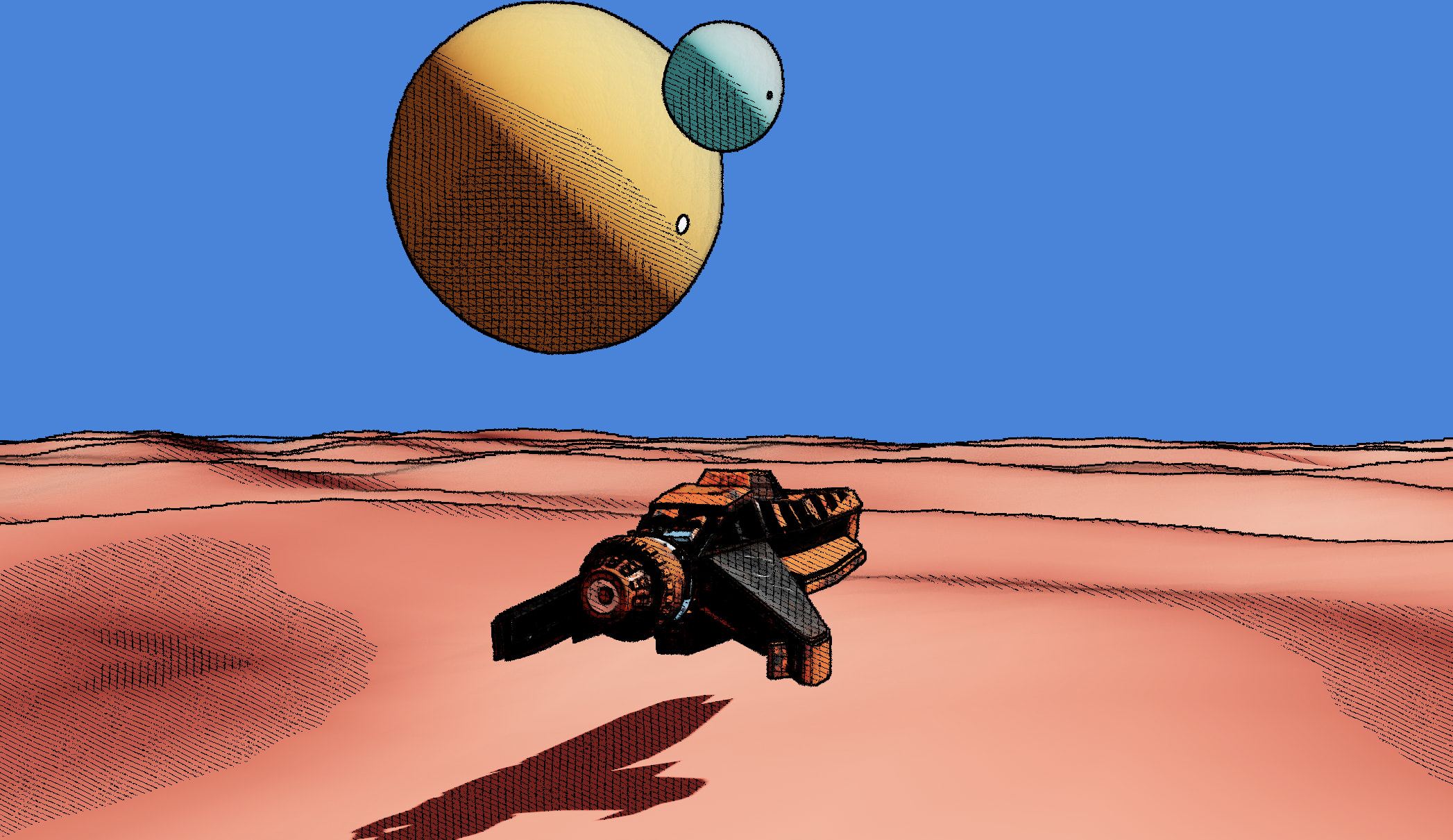

Thus, the Sobel filter had no way to draw all the outlines of the displaced ground mesh 🫠 which, to its own point of few, was nothing more than a flat plane. That is a clear pitfall of our implementation, and moreover one I only noticed while building the final showcase of this project...
@Cody_J_Bennett gave me a couple of alternatives like deriving the Normals from the depth data, or using a gbuffer but those seemed a bit too daunting for me at this stage (and to be honest I was quite tired as well) so I ended up choosing an "the easy way out": manually traversing the scene and assigning the ground its own custom Normal material that takes the displacement into account.
Traversing the scene manually to override materials with more flexibility
1//...2const materials = [];34gl.setRenderTarget(normalRenderTarget);56scene.traverse((obj) => {7if (obj.isMesh) {8materials.push(obj.material);9if (obj.name === 'ground') {10obj.material = GroundNormalMaterial; // <- takes displacement into account11obj.material.uniforms.uTime.value = clock.elapsedTime;12obj.material.uniforms.lightPosition.value = lightPosition;13} else {14obj.material = CustomNormalMaterial; // <- our standard normal material we built earlier15obj.material.uniforms.lightPosition.value = lightPosition;16}17}18});1920gl.render(scene, camera);2122scene.traverse((obj) => {23if (obj.isMesh) {24obj.material = materials.shift();25}26});27//...
I'm not the most proud of that one 😅, but it works: the displaced ground now features outlines at the right place and the whole scene comes together beautifully!


The demo below features all the techniques and workarounds I mentioned in this last part and showcases a reconstitution of my take on what a Moebius-worthy scene for the web should look like.
Through this attempt at reproducing the Moebius style, we learned how to build very pleasing stylized shaders and how we can apply them via post-processing, and on top of that, with custom shadows, outlines, and lighting patterns! I hope this exercise gave you confidence and inspiration to go beyond the physically based and emulate different art styles through your shader work.
Hope you'll have a lot of fun playing with this effect! In the meantime, I'll continue exploring other kinds of stylized shaders and post-processing effects that have been on my bucket list for way too long 😌.
Liked this article? Share it with a friend on Twitter or support me to take on more ambitious projects to write about. Have a question, feedback or simply wish to contact me privately? Shoot me a DM and I'll do my best to get back to you.
Have a wonderful day.
– Maxime
A detailed essay on the process of building a post-processing stylized shader reproducing the style of legendary artist Jean Giraud a.k.a Moebius for your React Three Fiber projects. In it, I detail the process of drawing outlines with a Sobel Filter as well as custom shadow and lighting patterns to bring a unique style to your WebGL scene.