Post-Processing Shaders as a Creative Medium
Spending the better part of 2024 learning new shader techniques and concepts through the lens of post-processing has been the spark I needed to come up with ever more intricate, detailed, and ambitious creative work. Not only do I now know the inner workings of specific styles like Moebius, Painting, or Retro, but it also got me to a point where I strengthened the many shader mental models I built along the years enough to experiment with new styles that I see online or that I envision in my mind.
That led me on a sort of creative spree for the past few months that originated from many creative developers, artists, and designers on Bluesky and Twitter such as: @dghez_, Polygon1993, @darkroomdevs, @hahajohnx, @samdape, 27-b (and many others sources listed throughout this article), whose works have, quite frankly, nerd-sniped me into reproducing or expanding their ideas into stylized shaders. Whether those featured complex pixelated patterns, trompe l'oeil, optical illusions, or surprising interactions, transcribing their art styles into shaders allowed me to not only sharpen my shader skills but also experiment with combining those effects in unique ways.
Through this process, I collected a few new shading tricks in my toolbox to share with you and, more importantly, new ways to reuse what I had learned in previous years in a new context. This is the reason why I wanted to write this article. In it, you'll see the many sources of inspiration that led to those beautiful post-processing effects, my train of thought to re-implement them, and the full-on recipe behind them so you can reproduce them, expand them, or simply get inspired to create your own.
I already explored pixelation in The Art of Dithering and Retro Shading for the Web where I introduced it alongside color quantization and dithering as it was a necessary effect to achieve a "retro style" akin to old video games on CRT displays.
However, this time I want to go beyond that and show you some of the many effects you can craft with this technique by literally sculpting pixels and creating intricate and elaborate patterns.
Pixelating your scene
As a reminder, let's re-examine the code that I used and still use to this day for all my pixelation work:
Sampling and pixelating a texture
1vec2 normalizedPixelSize = pixelSize / resolution;2vec2 uvPixel = normalizedPixelSize * floor(uv / normalizedPixelSize);34vec4 color = texture2D(inputBuffer, uvPixel);
- We first define a
pixelSizeas the number of pixels in height or width we want in a single "new pixel" for our final render/sampling. I tend to keep those as powers of 2:1, 2, 4, 8, 16, ... - We then normalize the
pixelSizebased on the resolution, which gives us the size of a single pixel in "UV coordinates" (ranging[(0, 0), (1, 1)]). This is necessary to keep our "new pixels" square no matter the window size. - We define a grid of cells by dividing our UV coordinates by the
normalizedPixelSize. - Adding the
floorcreates theblockeffect: the UV coordinates no longer vary smoothly across the screen but instead jump between fixed points. - Finally, we multiply by the
normalizedPixelSizeto convert the grid of cells to UV coordinates. - We can then use our newly mapped UV coordinates to sample our texture.
If this formula still feels overwhelming, the best is to break it down with an example:
Breakdown of pixelation code
1Example: If we have:2resolution = vec2(800, 600) // Screen size in pixels3pixelSize = vec2(8, 8) // We want 8x8 pixel blocks4uv = vec2(0.374, 0.567) // Current texture coordinate561. Calculate the size of each pixel block in normalized coordinates (0 to 1)7normalizedPixelSize = (8, 8) / (800, 600) = (0.01, 0.0133)89102. Snap the UV coordinate to the nearest pixel block grid11floor(uv / normalizedPixelSize) = floor((0.374, 0.567) / (0.01, 0.0133))12= floor((37.4, 42.6)) = (37, 42)1314Then multiply back by normalizedPixelSize15uvPixel = (0.37, 0.559)
I also built the widget below for you to see what happens when you apply this code to a texture/scene:
Shaping pixels
We could leave our pixelated output as such, but squares quickly get boring. Moreover, our cells have a lot of pixels we can use to draw interesting patterns, or even better, sculpt any shape we may want.
I saw this very cool Japanese receipt website made by @samdape last month, and I liked it so much that I recreated this pattern as a post-processing effect. I not only wanted it to work on top of everything and be dynamic but also thought it would be a great first example for this article, as it's an easy effect to break down with a lovely/original output.
saw this japanese receipt laying around & turned it into my website 🌀 https://t.co/TfdoXlNIb9 from idea to live in ~3h with @figma & @v0 https://t.co/lHniV7Lezo
Here is how I interpreted this effect by just looking at the screenshots of Sam's website:
- We have a pretty blocky-looking output, so we'll need to pixelate our
inputBufferby quite a bit. - Each cell is composed of horizontal black bars.
- The darker the area, the longer the bar.
- The lighter the area, the shorter the bar (or no bar).
With this in mind, we can leverage the pixelation formula we dissected just above and the luma of a given pixel to build this receipt effect.
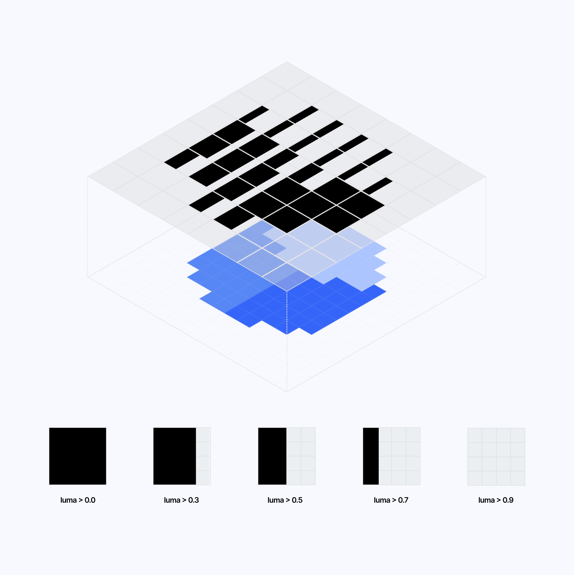
Receipt Bar fragment shader
1void mainImage(const in vec4 inputColor, const in vec2 uv, out vec4 outputColor) {2vec2 normalizedPixelSize = pixelSize / resolution;3float rowIndex = floor(uv.x / normalizedPixelSize.x);4vec2 uvPixel = normalizedPixelSize * floor(uv / normalizedPixelSize);56vec4 color = texture2D(inputBuffer, uvPixel);78float luma = dot(vec3(0.2126, 0.7152, 0.0722), color.rgb);910vec2 cellUV = fract(uv / normalizedPixelSize);1112float lineWidth = 0.0;1314if (luma > 0.0) {15lineWidth = 1.0;16}1718if (luma > 0.3) {19lineWidth = 0.7;20}2122if (luma > 0.5) {23lineWidth = 0.5;24}2526if (luma > 0.7) {27lineWidth = 0.3;28}2930if (luma > 0.9) {31lineWidth = 0.1;32}3334if (luma > 0.99) {35lineWidth = 0.0;36}3738float yStart = 0.05;39float yEnd = 0.95;4041if (cellUV.y > yStart && cellUV.y < yEnd && cellUV.x > 0.0 && cellUV.x < lineWidth) {42color = vec4(0.0, 0.0, 0.0, 1.0);43} else {44color = vec4(0.70,0.74,0.73, 1.0);45}46outputColor = color;47}
One thing that we should highlight in the code snippet above is this line:
1vec2 cellUV = fract(uv / normalizedPixelSize);
It returns the cellUV coordinates ranging again from [(0, 0), (1, 1)], giving us the relative position of a given pixel within each cell. This is the "magic line" that allows us to step inside each cell
and start shaping and sculpting them the way we want. In this specific case, we are conditionally turning the pixels within each cells black or white based on the lineWidth that's defined through the luma of the pixelated texture.
We will use similar techniques to define many patterns, some of which are depicted in the widget below which uses a similar principle to display those features:
Thanks to both the pixelation formula and this use of the fract glsl function, we established what is to me the two main pillars that we're going to keep encountering in most post-processing shaders:
- Remapping or distorting the UV coordinates
- Shape, sculpt, or tweak each cell individually to create a pattern
Both of these points are at work in the receipt effect in the demo below:
We can port this example to render a completely different effect while keeping approximately 90% of the code above unchanged. This time, let's try to build this dotted/halftone pattern used in this picture that I saw on Twitter a few months ago from once again @samdape:
The principle is the same, but with a few notable differences:
- We render circles in each cell
- For cells with luma above a certain threshold, we render a wide white circle centered in the middle of the cell
- For the rest, a smaller circle centered this time in the bottom left corner of the cell
Finally, as our final example for this section, why not try to rebuild Three.js' ASCII effect? This time, instead of creating our pattern within our fragment shader code, we will get it from an external texture containing all the characters for our ASCII palette where each character maps to a given cell luma:
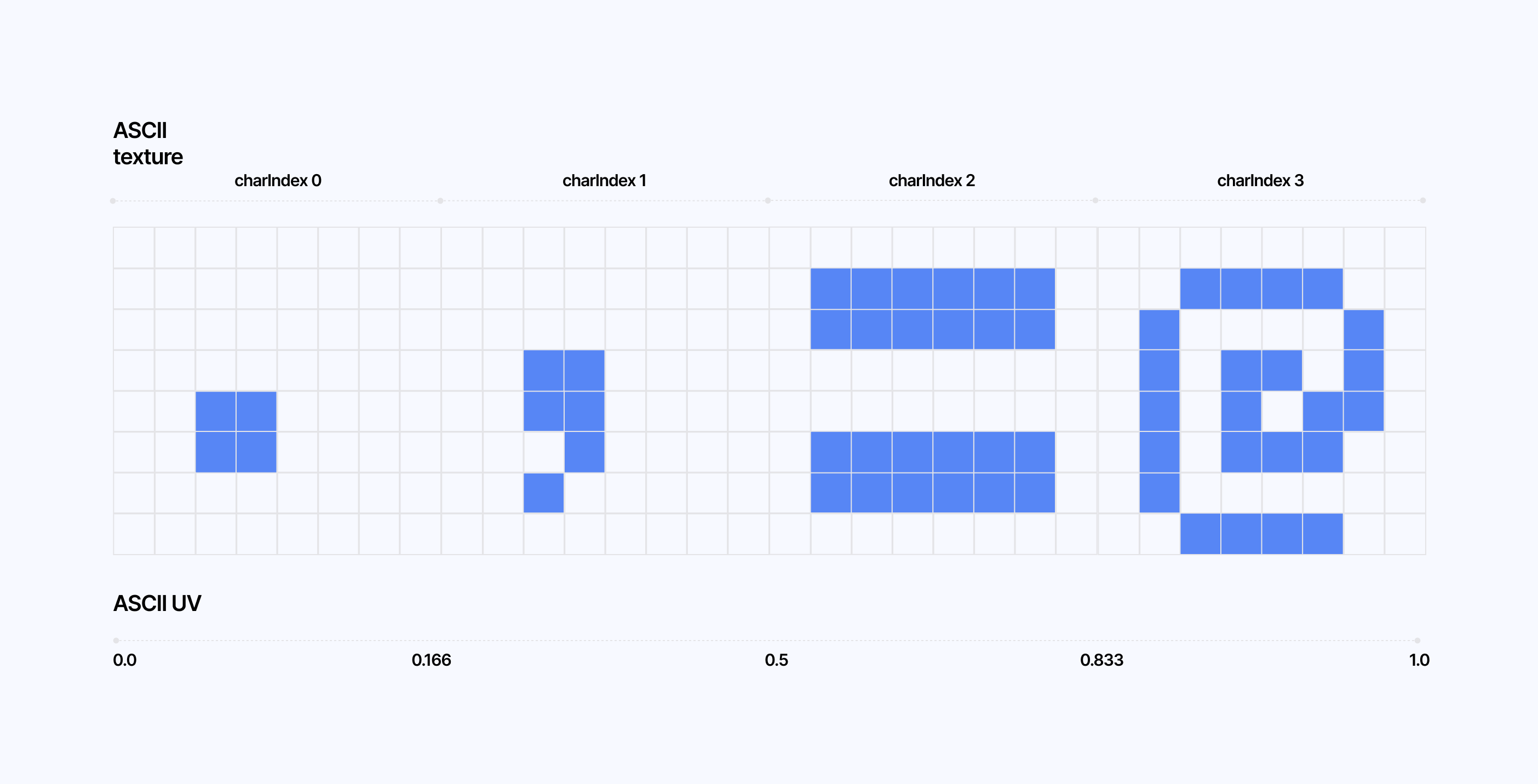
As for the implementation, we can create the texture of ASCII characters within our React Three Fiber code.
Creating our ASCII palette within our React Three Fiber scene
1//...23const ASCII_CHARS = './ノハメラマ木';45const ASCIIEffect = () => {67//...89useEffect(() => {10const CHAR_SIZE = pixelSize;11const canvas = document.createElement('canvas');12const ctx = canvas.getContext('2d');1314canvas.width = CHAR_SIZE * asciiChars.length;15canvas.height = CHAR_SIZE;1617ctx.fillStyle = 'black';18ctx.fillRect(0, 0, canvas.width, canvas.height);1920ctx.fillStyle = 'white';21ctx.font = \`\${CHAR_SIZE}px \${fontFamily}\`;22ctx.textBaseline = 'middle';23ctx.textAlign = 'center';2425asciiChars.split('').forEach((char, i) => {26ctx.fillText(char, (i + 0.5) * CHAR_SIZE, CHAR_SIZE / 2);27});2829const texture = new THREE.CanvasTexture(canvas);30texture.minFilter = THREE.NearestFilter;31texture.magFilter = THREE.NearestFilter;3233if (effectRef.current) {34effectRef.current.asciiTexture = texture;35effectRef.current.charCount = [asciiChars.length, 1];36effectRef.current.charSize = CHAR_SIZE;37}38}, [pixelSize, asciiChars]);3940//...41}
And then translate the luma of a given cell to an ASCII character by:
- converting the brightness (luma) to a character index
- creating UV coordinates from this index to sample the ASCII texture
Sampling ASCII character from the ASCII texture
1float charIndex = clamp(2floor(luma * (charCount.x - 1.0)),30.0,4charCount.x - 1.05);67vec2 asciiUV = vec2(8(charIndex + cellUV.x) / charCount.x,9cellUV.y10);1112float character = texture2D(asciiTexture, asciiUV).r;
On top of that, we can get inspired by the talented folks at @darkroomdevs, who, over the past few months, have shared a lot of ASCII work:
The demo below implements their take on ASCII and lets you define the characters you want to render in the effect.
This example is mainly here to show you that the source of your pattern can be varied:
- defined within your fragment shader
- defined in a texture and sampled within your fragment shader
Complex pixel patterns
Now that we've covered the basics from the previous section, let's explore more complex patterns.
This time, we'll be looking at some of John Provencher's (@hahajohnx) artwork, which we can adapt to glsl in multiple ways, a few of which involve concepts you may have seen in other contexts or other articles of mine:
- Signed Distance Functions (SDFs)
- Threshold Matrices
Like the previous demos, we can base the pixel pattern featured in John Provencher's work on the luma of a given cell:
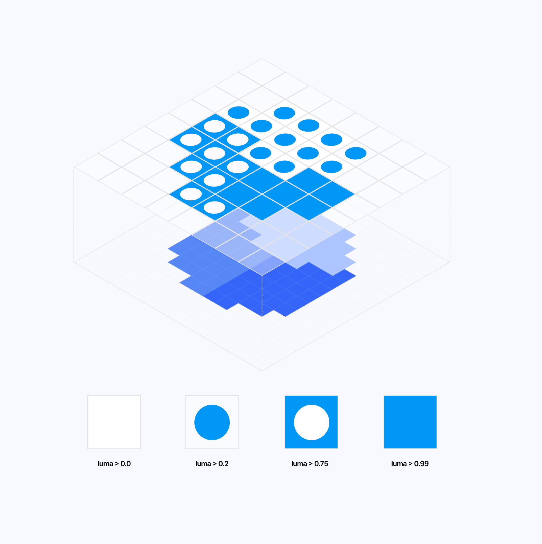
This time, let's use signed distance functions—specifically, the SDF of a circle—to reproduce the pattern:
Leveraging SDFs to render patterns within our cells
1float circleSDF(vec2 p) {2return length(p - 0.5);3}45// ...67float d = circleSDF(cellUV);89if (luma > 0.2) {10if (d < 0.3) {11color = vec4(0.0,0.31,0.933,1.0);12} else {13color = vec4(1.0,1.0,1.0,1.0);14}15}1617if(luma > 0.75) {18if(d < 0.3) {19color = vec4(1.0,1.0,1.0,1.0);20} else {21color = vec4(0.0,0.31,0.933,1.0);22}23}
This way of defining pixel patterns allows for a large set of patterns. With enough pixels to work within a cell, we can display any shape with an equivalent 2D SDF. You can try it yourself in the demo below, where I defined several extra functions like crossSDF or triangleSDF:
If you want to define patterns that are impossible to write via an SDF or simply enjoy the elegance of having a single matrix to render all the patterns you need: you may be interested in leveraging custom threshold matrices for your effect.
Akin to dithering, this method lets you define the luma thresholds within one or multiple matrices, which we can then use to compare with the luma of the pixel within a given cell. If the pixel's luma is above the threshold value defined in the matrix, it's turned on; otherwise, it remains turned off.
The widget below lets you visualize this principle and edit the values defined within the threshold matrix to create any pattern you want.
Using this technique, we can expand upon Provencher's work and create more patterns. Among those I enjoyed implementing were the following:
stripeswhich uses two threshold matricesweavewhich creates a complex pattern with only a single threshold matrix!
Defining custom threshold matrices to render different cell patterns based on luma
1if(pattern == 0) {2const float stripesMatrix[64] = float[64](30.2, 1.0, 1.0, 0.2, 0.2, 1.0, 1.0, 0.2,40.2, 0.2, 1.0, 1.0, 0.2, 0.2, 1.0, 1.0,51.0, 0.2, 0.2, 1.0, 1.0, 0.2, 0.2, 1.0,61.0, 1.0, 0.2, 0.2, 1.0, 1.0, 0.2, 0.2,70.2, 1.0, 1.0, 0.2, 0.2, 1.0, 1.0, 0.2,80.2, 0.2, 1.0, 1.0, 0.2, 0.2, 1.0, 1.0,91.0, 0.2, 0.2, 1.0, 1.0, 0.2, 0.2, 1.0,101.0, 1.0, 0.2, 0.2, 1.0, 1.0, 0.2, 0.211);1213const float crossStripeMatrix[64] = float[64](141.0, 0.2, 0.2, 0.2, 0.2, 0.2, 0.2, 1.0,150.2, 1.0, 0.2, 0.2, 0.2, 0.2, 1.0, 0.2,160.2, 0.2, 1.0, 0.2, 0.2, 1.0, 0.2, 0.2,170.2, 0.2, 0.2, 1.0, 1.0, 0.2, 0.2, 0.2,180.2, 0.2, 0.2, 1.0, 1.0, 0.2, 0.2, 0.2,190.2, 0.2, 1.0, 0.2, 0.2, 1.0, 0.2, 0.2,200.2, 1.0, 0.2, 0.2, 0.2, 0.2, 1.0, 0.2,211.0, 0.2, 0.2, 0.2, 0.2, 0.2, 0.2, 1.022);2324int x = int(cellUV.x * 8.0);25int y = int(cellUV.y * 8.0);26int index = y * 8 + x;2728if(luma < 0.6) {29color = (stripesMatrix[index] > luma) ? vec4(1.0) : vec4(0.0, 0.31, 0.933, 1.0);30} else {31color = (crossStripeMatrix[index] > luma) ? vec4(1.0) : vec4(0.0, 0.31, 0.933, 1.0);32}33}3435if(pattern == 1) {36const float sineMatrix[64] = float[64](370.99, 0.75, 0.2, 0.2, 0.2, 0.2, 0.99, 0.99,380.99, 0.99, 0.75, 0.2, 0.2, 0.99, 0.99, 0.75,390.2, 0.99, 0.99, 0.75, 0.99, 0.99, 0.2, 0.2,400.2, 0.2, 0.99, 0.99, 0.99, 0.2, 0.2, 0.2,410.2, 0.2, 0.2, 0.99, 0.99, 0.99, 0.2, 0.2,420.2, 0.2, 0.99, 0.99, 0.75, 0.99, 0.99, 0.2,430.75, 0.99, 0.99, 0.2, 0.2, 0.75, 0.99, 0.99,440.99, 0.99, 0.2, 0.2, 0.2, 0.2, 0.75, 0.9945);4647int x = int(cellUV.x * 8.0);48int y = int(cellUV.y * 8.0);49int index = y * 8 + x;50color = (sineMatrix[index] > luma) ? vec4(1.0) : vec4(0.0, 0.31, 0.933, 1.0);51}
We can see the result of those matrices yield in the demo below:
Mimicking close to real life/physical textures and effects is my favorite thing to achieve with post-processing. With a few simple techniques, we can make our output appear to have depth, texture, and lighting. Applied right, these techniques can transform our scenes, making them appear as if they were made out of Legos or woven like Crochet, to look like they are displayed on an LED panel or behind a slick pane of frosted glass.
This section goes through the details behind a few of my favorite post-processing effects that I came up with recently. We'll dissect each technique used, and see how combining them and tweaking them the right way can yield beautiful trompe l'oeil or optical illusion effects running right in your browser.
Stagged LED cell panel
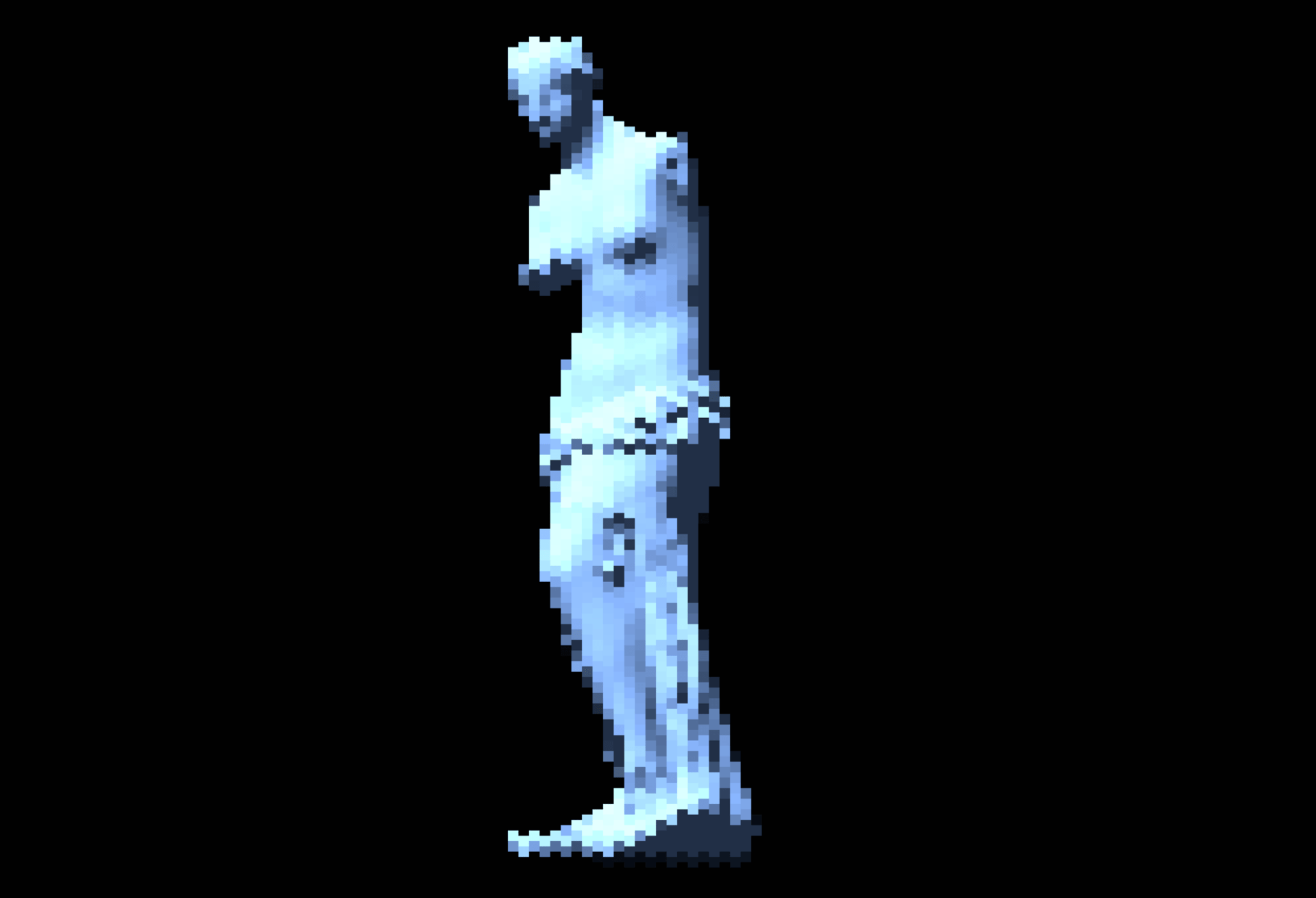
This section features the technique behind my Pixel Statue demo, which aimed to mimic a staggered LED cell panel. I was originally inspired by the many LED panels I saw during my recent trip to Japan, whether used on trains or in public spaces to display ads.
The main trick for this scene is to stagger our cells, and eventually pixels within our cells, to create a more elaborate LED cell matrix. This is done by offsetting the UV coordinates before remapping them.
Staggering pixels
1float maskStagger = 0.5;23vec2 normalizedPixelSize = pixelSize / resolution;4vec2 coord = uv/normalizedPixelSize;56float columnStagger = mod(floor(coord.x), 2.0) * maskStagger;78vec2 offsetUV = uv;9offsetUV.y += columnStagger * normalizedPixelSize.y;1011vec2 uvPixel = normalizedPixelSize * floor(offsetUV / normalizedPixelSize);
This specific code adds an arbitrary vertical offset to every odd column of cells.
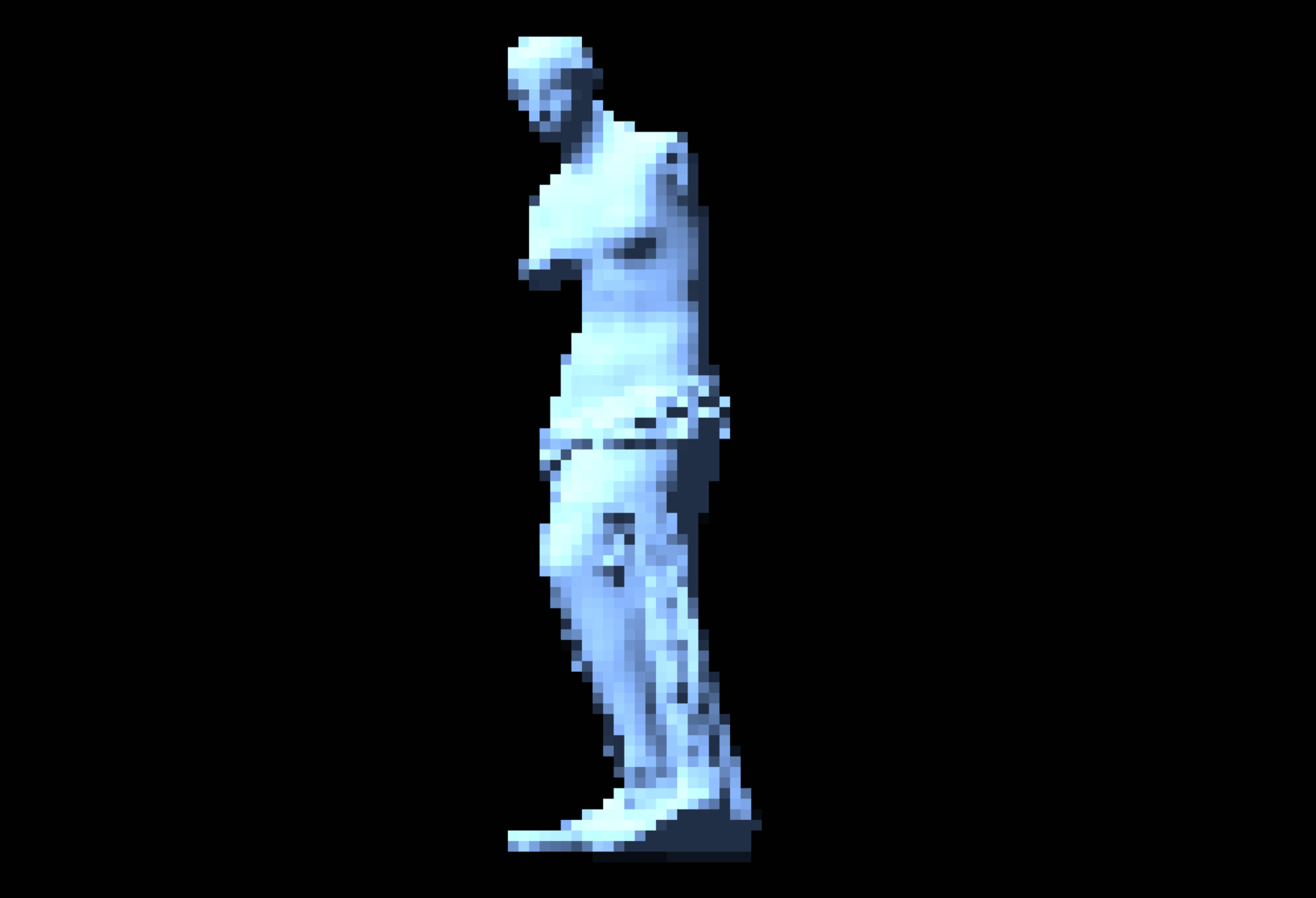
Yet, we can push things further and introduce offsets at the "sub-cell level" to create an even more intricate effect. We could, for instance, split our cell into three sub-cells as we did for the CRT effect in my Dithering article and stagger each of those sub-cells.
Defining sub-pixels with offset
1vec2 normalizedPixelSize = pixelSize / resolution;2vec2 coord = uv/normalizedPixelSize;34float columnStagger = mod(floor(coord.x), 2.0) * maskStagger;56vec2 subcoord = coord * vec2(3,1);7float subPixelIndex = mod(floor(subcoord.x), 3.0);8float subPixelStagger = subPixelIndex * maskStagger;910vec2 offsetUV = uv;11offsetUV.y += (columnStagger + subPixelStagger) * normalizedPixelSize.y;
Once we remap those staggered UVs, it will look as if you cut each of the cells into three vertical thin slices that you can manipulate at will.

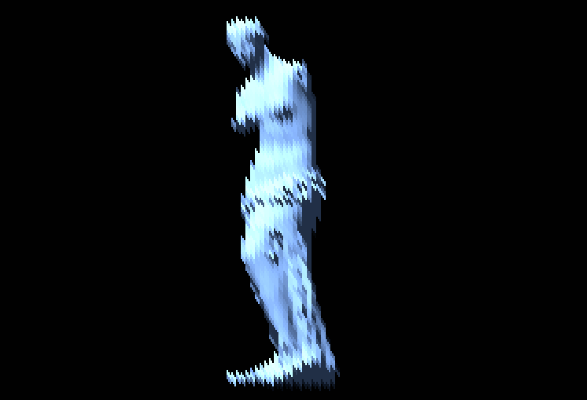
We can also use this offset within each cell of our effect to introduce the same staggered offset to any pattern we may want to render within them. In this case, we want our LED cells to be relatively visible, thus having a mask border around each sub-pixel is necessary. The trick to adding this border is to create a subCellUV vector by taking the fractional of the subcoord that ranges from (-1, -1) to (1, 1) to create a symmetrical border that surrounds the cell.
Drawing a black border around each staggered sub-cell
1vec2 cellOffset = vec2(0.0, columnStagger + subPixelStagger);2vec2 subCellUV = fract(subcoord + cellOffset) * 2.0 - 1.0;34float mask = 1.0;5vec2 border = 1.0 - subCellUV * subCellUV * (MASK_BORDER - luma * 0.25);6mask *= border.x * border.y;7float maskStrength = smoothstep(0.0, 0.95, mask);89color += 0.005;10color.rgb *= 1.0 + (maskStrength - 1.0) * MASK_INTENSITY;
Finally, to polish this LED panel illusion, we can make the darker pixels in the background somewhat visible by increasing all color channels by a small amount.
Woven Crochet Effect
Speaking of staggered columns/rows and offsets, my crochet post-processing effect uses a similar technique to create a more organic look and feel for its knitted fabric illusion. This time, however, the offset is applied to the cellUV coordinates themselves.
The inspiration behind this effect comes from a very neat Blender plugin that I saw on Twitter way back in November 2024:
Unlike the LED panel effect, where we want to physically move pixels by offsetting the sampling coordinates, the crochet effect maintains the underlying pixelated texture grid while only shifting the pattern mask that creates the knitted appearance.
Offset defined for our crochet effect
1vec2 normalizedPixelSize = pixelSize / resolution;2vec2 uvPixel = normalizedPixelSize * floor(uv / normalizedPixelSize);3vec4 color = texture(inputBuffer, uvPixel);45vec2 cellPosition = floor(uv / normalizedPixelSize); // coordinate of the current cell6vec2 cellUV = fract(uv / normalizedPixelSize);78float rowOffset = sin((random(vec2(0.0, uvPixel.y)) - 0.5) * 0.25);9cellUV.x += rowOffset;
As for the pattern, I opted for a simple ellipsis rotated -65 degrees for even cells and 65 degrees for odd cells.
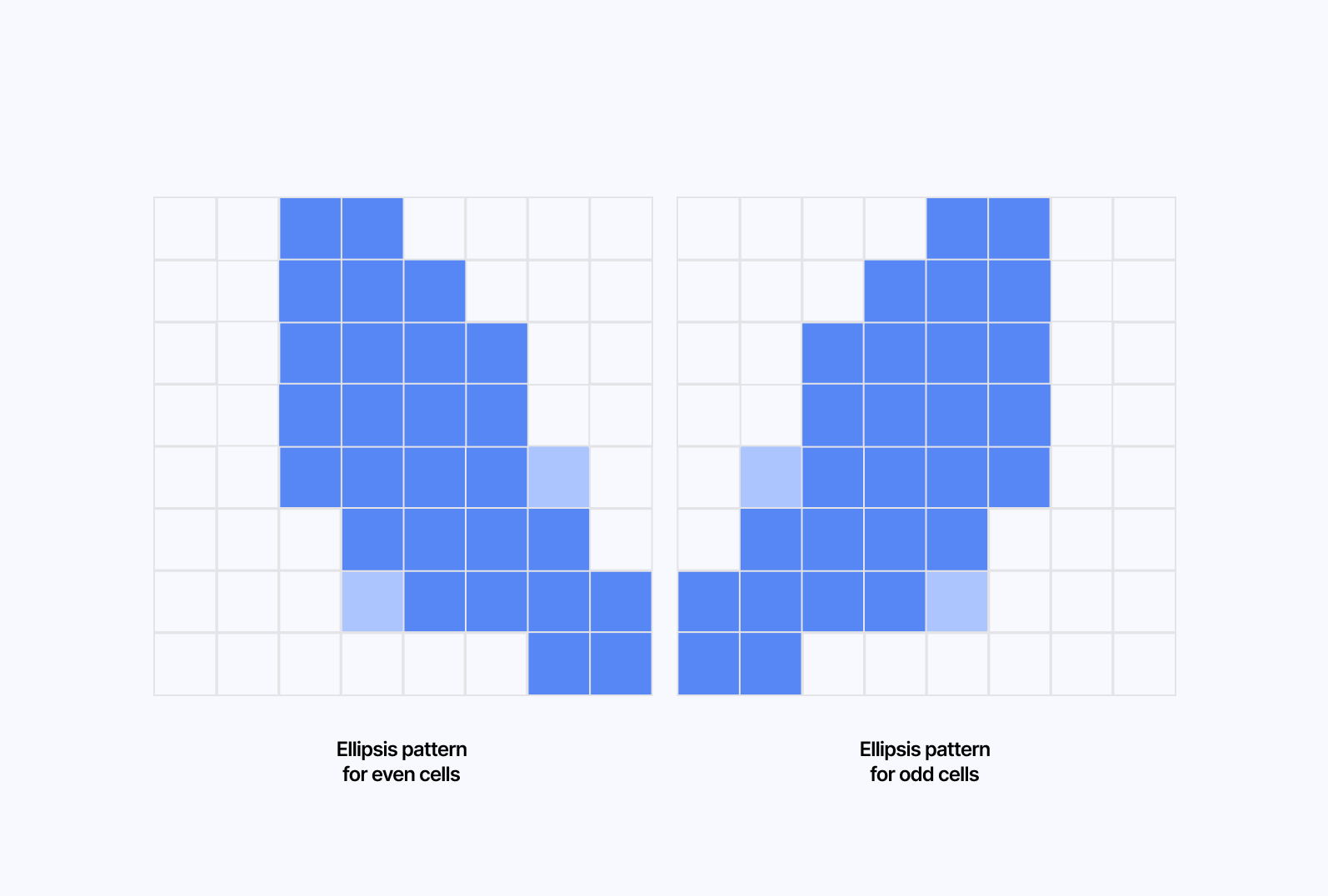
Getting an ellipsis rotated as such in GLSL is luckily straightforward:
- We use a standard rotation matrix around the center of the cell to have it positioned at an angle
1float isAlternate = mod(cellPosition.x, 2.0);2float angle = isAlternate == 0.0 ? radians(-65.0) : radians(65.0);34vec2 rotated = vec2(5center.x * cos(angle) - center.y * sin(angle),6center.x * sin(angle) + center.y * cos(angle)7);
- We create the ellipsis around said center by calculating the distance between the current pixel and the center of the cell, stretching the shape vertically and shifting it up. Eventually, we use that distance with the
smoothstepfunction to create the elliptical shape with soft edges.
1float aspectRatio = 1.55;2float ellipse = length(vec2(rotated.x, rotated.y * aspectRatio - 0.075));3color.rgb *= smoothstep(0.2, 1.0, 1.0 - ellipse);
Once we reach that stage, 90% of the work is done, we just need to add a few more details. Here's a list of functions and effects that compound once added to the pattern and make our crochet shader look like fabric:
- Apply noise to the center of each cell in the crochet pattern so that the edges of each ellipsis look more rough.
- Create a stripe pattern for each ellipsis to mimic the fabric. Far from perfect but good enough
- Add a slight hue shift to the color of each ellipse to give it a more organic look, as the thread color may vary.
Lego bricks
This one was a fun effect to build. For one, it has to do with Legos, which I love, but also, it is a simple yet elegant post-processing effect:
- It uses your classic pixelation logic that we went through in the first part
- The stud at the center of each cell is a lighting illusion.
To create the stud at the center of the cell, we can reuse what we learned about the Blinn-Phong lighting model in Refraction, dispersion, and other shader light effects.
Defining diffuse lighting for our 2D lego brick effect
1float lighting = dot(normalize(cellUV - vec2(0.5)), lightPosition) * 0.7;2float dis = abs(distance(cellUV, vec2(0.5)) * 2.0 - 0.5);3color.rgb *= smoothstep(0.1, 0.0, dis) * lighting + 1.0;
Then, from the center of the cell:
- We calculate the distance between each point and the center.
- Create a soft circular edge using
smoothstep. - Combine it with the lighting value.
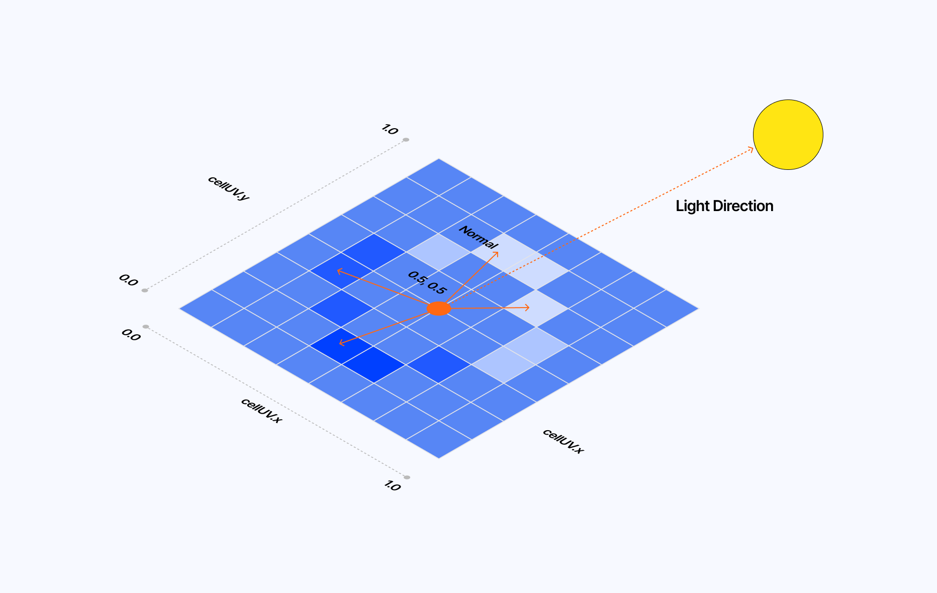
With this, each of our cells features a circular shaded stud in the center, just like a 1x1 Lego brick! To polish the effect, we can reuse constructs we've seen previously in this article or other pieces of content I got to write in the past:
- We can use color quantization to limit the color palette of this effect. Lego pieces come in a limited set of colors so it is fair to impose a limit here. I showcased how color quantization works in The Art of Dithering and Retro Shading for the Web
- We can add a subtle border around each cell by reusing the same logic introduced in the LED panel effect, giving the impression that the final output is a mosaic of single-stud Lego pieces.
- Finally, we can add a dash of hue shift to bring some variety in the colors used, especially for the scene's background, which may only feature a single color.
- To top it all off, we can clamp the min and max of each color channel slightly to avoid having Lego pieces that are either too dark or too bright, as the stud would not be very visible in those cases.
Fluted & frosted glass
There has been a recent trend in art and media, whether digital or printed, to use fluted glass to add what I'd call physically-based distortions to an image. As a post-processing effect, it's really enticing as it truly feels like a layer of frosted glass is placed between you the viewer and the scene.
This effect might feel like a departure from the ones we've seen so far, as it's the only one in this post that will not feature pixelation. Yet, the techniques and principles behind it are similar to the ones used in some of our previous examples:
- UV Distortion
- Blinn-Phong lighting model
To build this effect, let's first see how the shape of the pane of glass gives us the mathematical function that describes the distortion. We want fluted glass so our distortion will look like a sine wave such as: sin(uv.x * PI). When looking at this shape, we can expect that the distortion will be as follows:
- Minimum at the peaks and valleys of the wave as the surface is flat.
- Maximum in between when the curve grows or decreases.
Through this reasoning, we can define the distortion as the derivative of the function defining our fluted glass shape, which, in this case, would be: cos(uv.x * PI) * PI.
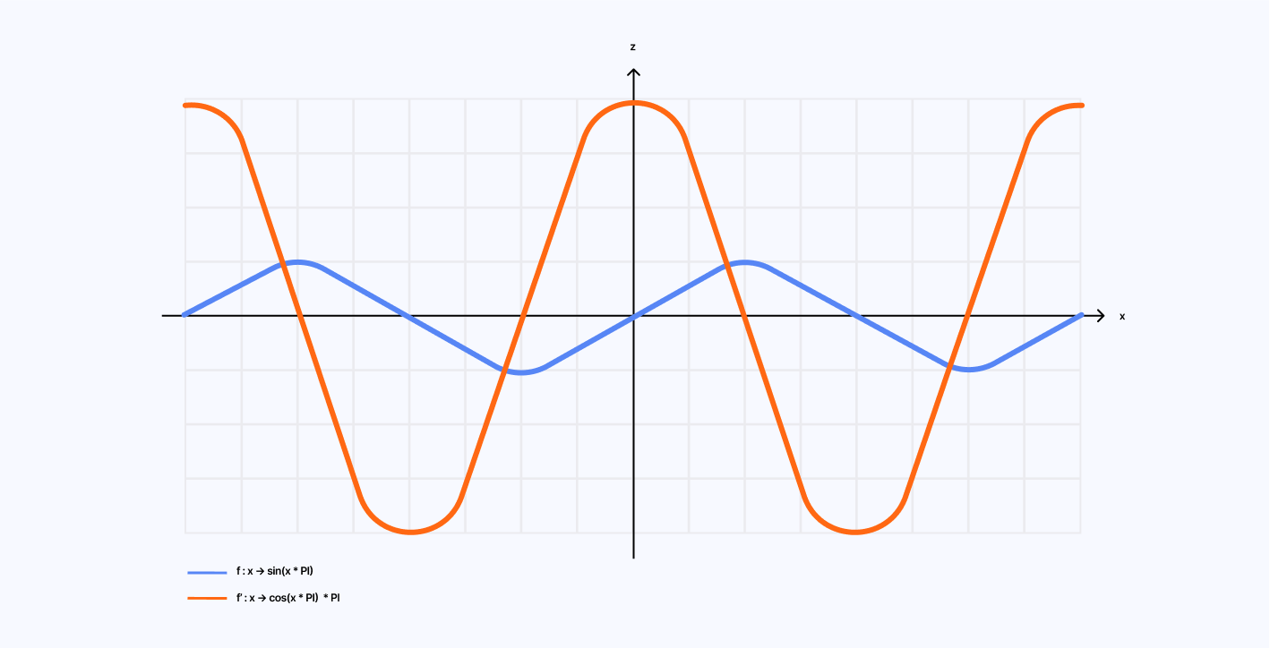
Translating those mathematical concepts into code yields the following result:
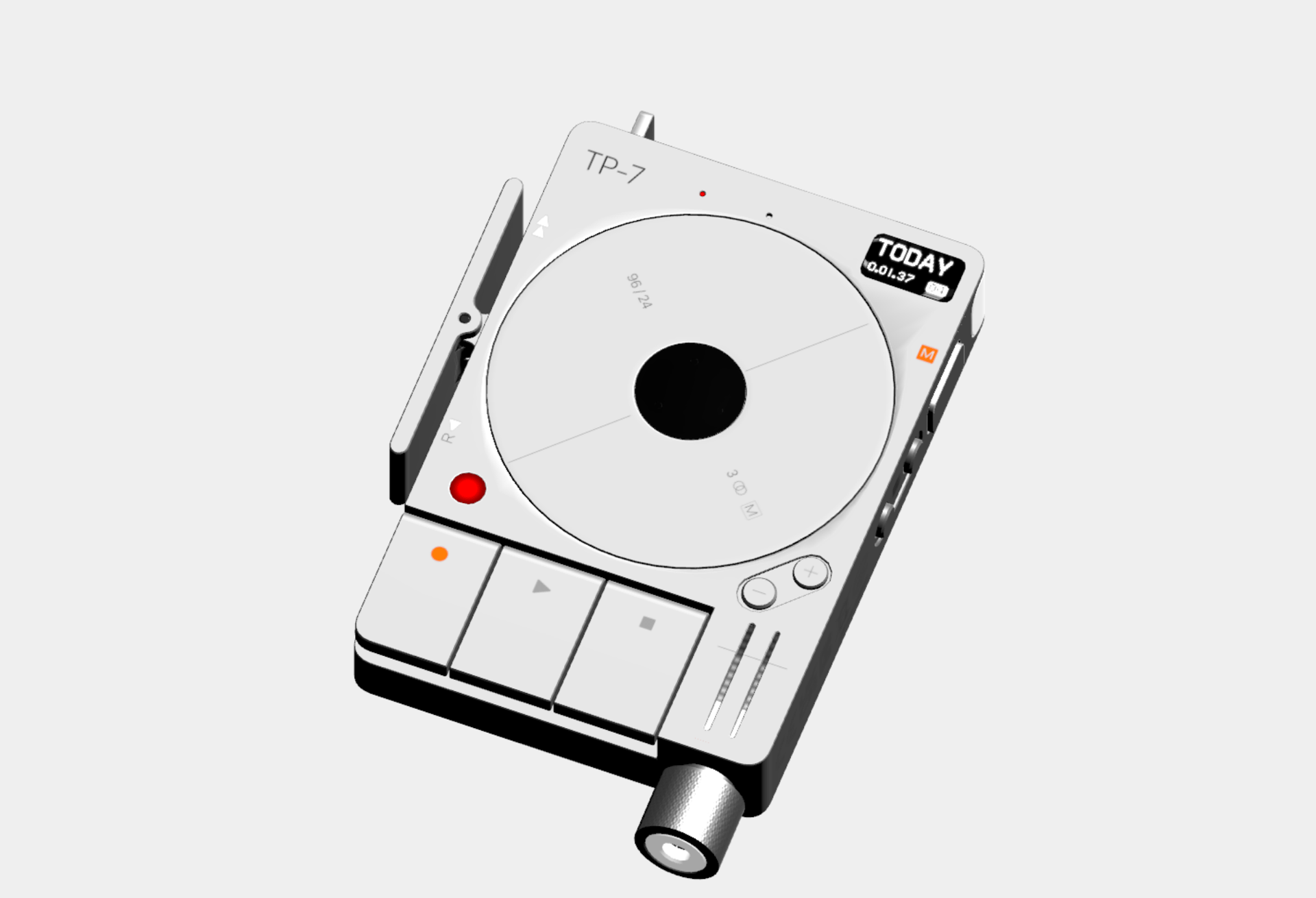
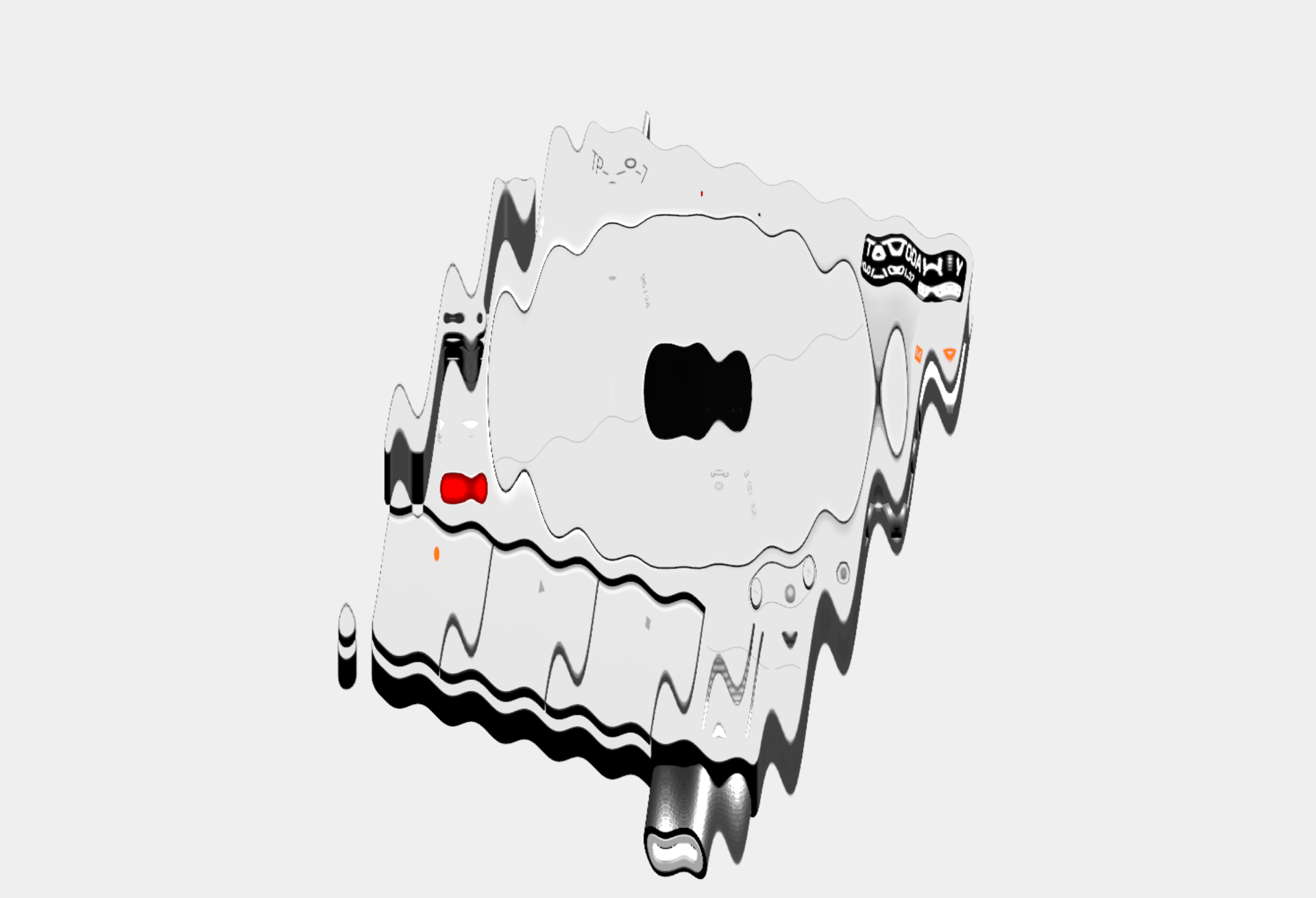
Simple fluted glass-like distortion
1float fluteCount = 25.0;2float flutePosition = fract(uv.x * fluteCount + 0.5);34vec2 distortion = vec2(cos(flutePosition * PI * 2.0) * PI * 0.15, 0.0);56vec2 distortedUV = uv + distortion * distortionAmount;
This is great, but, we're not seeing any glass yet. The illusion we're trying to build relies on light to give it its glass texture, so we need to convert our derivative, which tells us "how steep is the surface/how intense is the distortion", into a vector that tells "which way does the surface point?", i.e. a normal, which is what we need for light calculations. Our effect is a curved piece of glass, so the normal vector will point towards us the viewer, slightly sideways in the slopes and straight towards us in the valleys and peaks of the curve.
We already have the x component of our normal vector, the y component is 0 for our case, so we can deduce the z component using the formula normal.x² + normal.y² + normal.z² = 1.
From distortion to lighting
1float fluteCount = 25.0;2float flutePosition = fract(uv.x * fluteCount + 0.5);34vec3 normal = vec3(0.0);5normal.x = cos(flutePosition * PI * 2.0) * PI * 0.15;6normal.y = 0.0;7normal.z = sqrt(1.0 - normal.x * normal.x);8normal = normalize(normal);910vec3 lightDir = normalize(vec3(lightPosition));11float diffuse = max(dot(normal, lightDir), 0.0);12float specular = pow(max(dot(reflect(-lightDir, normal), vec3(0.0, 0.0, 1.0)), 32.0);1314vec2 distortedUV = uv + normal.xy * distortionAmount;
Finally, to polish things up, we can add a couple of effects to this shader to make it as realistic as possible:
- Gaussian Blur, to give some more depth.
- A dash of noise to create a frosted glass effect.
- Some slight chromatic dispersion, because why not.
So far, we have considered post-processing effects solely as mere image filters, but we can achieve more with them. Adding a dash of interactivity into the mix, whether time-based or by leveraging the cursor of the user for example, can yield some very unique and delightful results and make your effects really stand out.
Progressive Depixelation
I like leveraging pixelation in many of my post-processing experiments, so it felt natural to start my journey into dynamic effects with this progressive pixel loading one. We can easily make the pixelSize depend on time or an arbitrary progress uniform, but even more challenging is to have the effect progressively de-pixelated the screen row-by-row, pixel-by-pixel.
The diagram below illustrates my original sketch showcasing how this effect would eventually work:
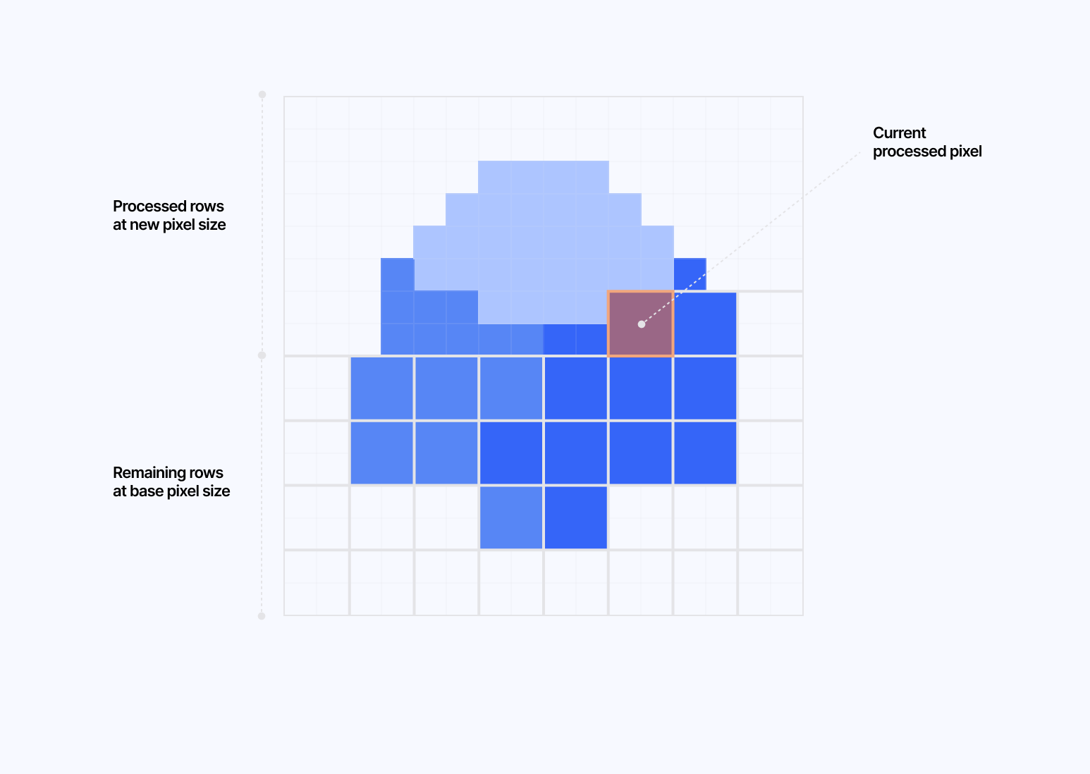
To achieve this, the trick consists of:
- Setting a concept of
levelbased on the originalbasePixelSizeand how far along in the transition we are. - Each level representing "a power of 2" and going down 1 level at a time as the
basePixelSizeis decreasing. - Calculating the number of pixels per row/column and the current row/column processed at the current level.
- Get the row and position within the row for a given UV.
Main variables defined for our depixelation effect
1float LEVELS = 5.0;23float basePixelSize = pow(2.0, LEVELS);4float currentLevel = floor(progress * LEVELS);56float currentPixelSize = max(basePixelSize / pow(2.0, currentLevel), 1.0);78float currentPixelsPerRow = ceil(resolution.x / currentPixelSize);9float currentPixelsPerCol = ceil(resolution.y / currentPixelSize);10float currentTotalPixels = currentPixelsPerRow * currentPixelsPerCol;1112float levelProgress = fract(progress * LEVELS) * currentTotalPixels;13float currentRowInLevel = floor(levelProgress / currentPixelsPerRow);14float currentPixelInRow = mod(levelProgress, currentPixelsPerRow);1516vec2 gridPos = floor(uv * resolution / currentPixelSize);17float row = floor(currentPixelsPerCol - gridPos.y - 1.0);18float posInRow = floor(gridPos.x);
Once we have all that defined, it's just a matter of reusing our pixelation effect from part 1, but this time conditionally:
- If the a row of pixels is within any previous row that's already been processed: we should use the updated pixel size (e.g. if we started at
128, then it should be64). - If we're on the currently processing row AND the pixel's horizontal position is less than or equal to how far we've processed in this row: we should use the updated pixel size as well (e.g. if we started at
128, then it should be64). - Else we should be on the old pixel size (
128). - We can also add a final case for when we reach a pixel size inferior to or equal to
1.
The demo below showcases the effect linked to a progress uniform. You could also hook it up to a time uniform if you ever wished to have it trigger on page load or any other event without needing a user interaction.
Pixelating Mouse Trail
For this section, I have to shoutout the incredible work of @dghez_ for his work on rosehip.xyz and 27b's lab section, who both had a take on a pixelating mouse trail effect that increases the pixel size and distorts the underlying image as you move your cursor across the screen.
I had previously built a reusable MouseTrail component that I used in some of my shader experiments and I thought to myself that, to achieve a similar effect as the one in the examples above, I could repurpose it and put its output inside a Frame Buffer Object (FBO) to feed the resulting texture as an argument to my pixelating effect. The texutre itself would be visible as the user moves the cursor, so I'd only have to make the pixel size and distortion a function of the speed and direction of said cursor.
Using React Three Fiber's createPortal function, we can render the MouseTrail component demoed above in a separate scene, and dedicate a FBO to store its output as a texture:
Rendering the MouseTrail component in a portal and storing its output as a texture
1const PixelatingMouseTrail = () => {2const mouseTrail = useMemo(() => new THREE.Scene(), []);3const mouseTrailFBO = useFBO({4minFilter: THREE.LinearFilter,5magFilter: THREE.LinearFilter,6format: THREE.RGBAFormat,7type: THREE.FloatType,8});910//...11useFrame((state) => {12const { gl, camera } = state;1314//...1516gl.setRenderTarget(mouseTrailFBO);17gl.render(mouseTrail, camera);18gl.setRenderTarget(null);1920//...21});2223const { camera } = useThree();2425return (26<>27{createPortal(<MouseTrail mouse={smoothedMouse} />, mouseTrail, {28camera,29})}30<group ref={spaceshipRef}>31<Spaceship />32</group>33<PixelatingMouseTrailEffect34mouseTrailTexture={mouseTrailFBO.texture}35mouse={smoothedMouse.current}36mouseDirection={smoothedMouseDirection.current}37/>38</>39);40};
We can then pass this mouseTrailTexture as a uniform to our shader effect, and use it to have a variable pixelization based on:
- The distance between the current pixel and the mouse, ranging from
1.0if it is close to the mouse to0.0if it is far away. - The intensity of the mouse trail, its
rgcolor channel, since its color ranges fromred(vertical mouse movements) togreen(horizontal mouse movements) - With this, we can sample a pixelated version of the mouse trail, which we can use to offset our main UV coordinates. Once again, we'll reuse the pixelation logic we detailed in the first section.
Pixelation based on the mouse trail texture
1uniform sampler2D mouseTrailTexture;2uniform vec2 mouse;3uniform vec2 mouseDirection;45void mainImage(const in vec4 inputColor, const in vec2 uv, out vec4 outputColor) {6vec4 mouseTrailOG = texture2D(mouseTrailTexture, uv);7float distanceToCenter = 1.-distance(uv, mouse);89float pixelSize = 32.0 + length(mouseTrailOG.rg) * distanceToCenter;10vec2 normalizedPixelSize = pixelSize / resolution;11vec2 uvPixel = normalizedPixelSize * floor(uv / normalizedPixelSize);12vec4 mouseTrail = texture2D(mouseTrailTexture, uvPixel);1314// Disort the texture based on the mouse direction15vec2 textureUV = uv;16textureUV -= mouseTrail.rg * distanceToCenter * mouseDirection;1718vec4 color = texture2D(inputBuffer, textureUV);19vec4 trailColor = vec4(0.9, 0.9, 0.9, 0.1);20outputColor = max(color, mix(color, trailColor, mouseTrail.r));21}
Finally, those distorted/offset UV coordinates can be used to sample the main scene:
This is one of the many examples of incorporating dynamic/variable pixelation as an effect. You could pass any texture to this, such as a Perlin Noise, a Fractal Brownian Motion noise, etc. The possibilities in terms of dynamic post-processing are truly endless. The best thing to do, as you may have guessed by now, is simply to try more things you've learned on your own shader journey and to combine them with the ideas of this article in a fun and unique way.
Each post-processing effect detailed in this post could have deserved its own article, but I thought it would be more interesting to look at them as a whole, as they share the same tricks and techniques despite yielding different outputs. This highlights the value of blending ideas and concepts to see what emerges as you learn more about shaders, develop your style, and discover the aesthetics that resonate with you.
When people come to me and ask, "How do you learn about/build those things?" what you saw in this blog post (waving arms around) is what I spend some of my free time doing. The added bonus of doing it with post-processing is that it allows me to experiment with ideas quicker, as it's a simple 2D canvas on which you can paint pixels in any way you want.
A follow-up goal of mine for post-processing would be to make those shader bits more composable, à la Lygia, and who knows, maybe build my own FX package (?). For now, my main focus will be to transition some of those effects to WebGPU as it would be a nice entry point into learning about compute shaders and the other new concepts brought by this new API. That topic, however, will be for another time 😄 in the meantime, I'll be on the lookout for your own creative post-processing effects to show up on my Twitter or Bluesky timeline using everything you learned in this post, and if done well enough, maybe you'll get me to spend some of my time trying to reproduce them.