Refraction, dispersion, and other shader light effects
Since my very first lines of React Three Fiber and shader code, I've been obsessed with light and how to reproduce some of its physical properties to add some delight to my 3D scenes ✨. I gathered countless examples of renders featuring those effects in my inspiration board, but one of them that always struck me as incredible was chromatic dispersion.
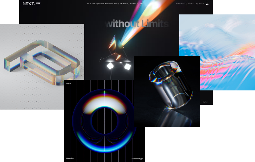
While most of those are renders or use specific shaders to emulate the dispersion, I really wanted to see if it was possible to reproduce this light effect along with others on the web by staying as close as possible to the physics of light and how it interacts with a mesh while keeping it real-time. Despite the complexity of the problem and an increasingly deep rabbit hole, I've since then somewhat achieved this goal, and I'm going to tell you all about that in this blog post!
In this article, I'll go through the steps I took to build a shader material with a pleasing dispersion effect through refraction, chromatic aberration, specular, and other fascinating light effects. You'll see that, with some math and well-positioned light rays, you can get something truly magical 🪄.
Bending light with refraction
Achieving a realistic refraction effect requires first to make our mesh's material transparent. There are many ways to obtain this transparency effect with shaders, but for this article, I'll focus on one that I like quite a lot: using Frame Buffer Object
Transparent mesh with FBO
To make our mesh transparent: we perform "multiple passes" in our render loop, i.e. for each frame. In the diagram below, I illustrated what each phase achieves and what we end up rendering within our Frame Buffer Object:
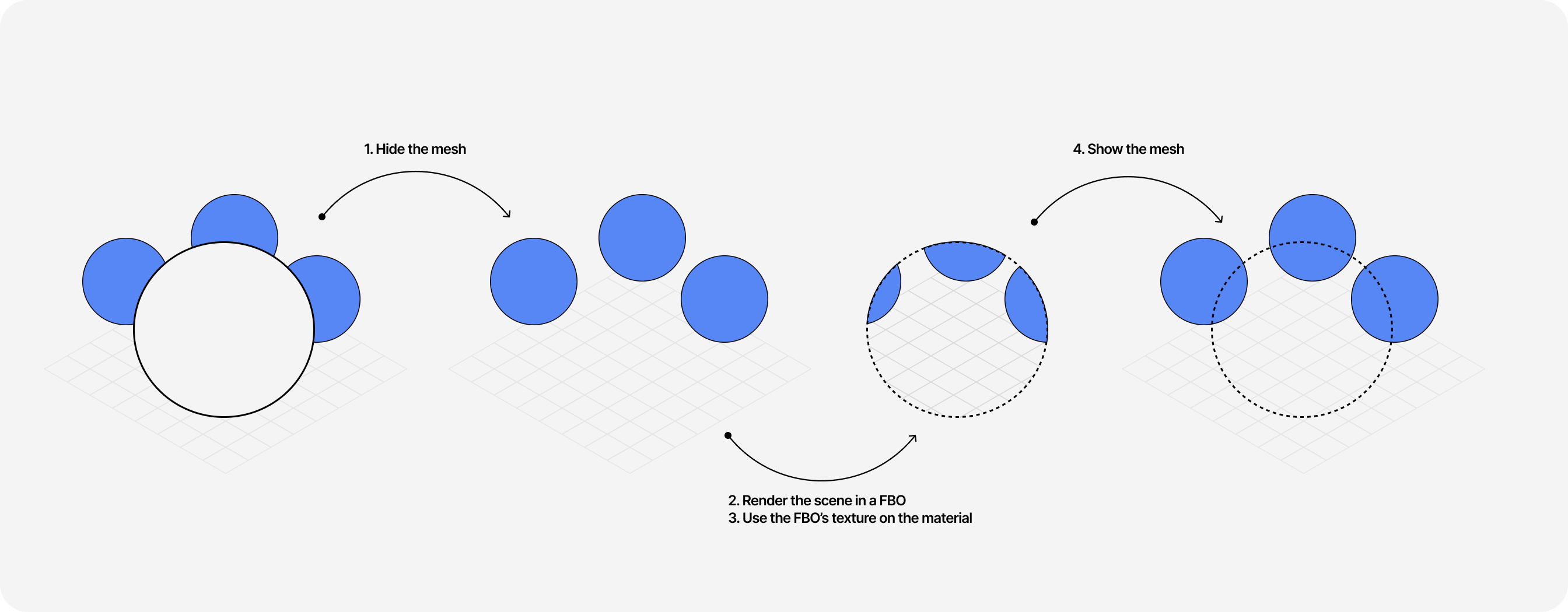
- First, we hide our mesh by setting the visibility prop of our material to
false. - We set the render target to the Frame Buffer Object.
- We take a snapshot of our entire scene (the other meshes, the background, etc.) by rendering it in the render target.
- We set the render target back to its original value of null.
- We pass the texture data of our Frame Buffer Object to the mesh's material fragment shader using a uniform where it will be read and displayed.
- We show our mesh by setting the visibility prop of our material to
true.
To do that, we can use React Three Fiber's handy useFrame hook so we can perform all those operations for each frame, allowing us to achieve real-time transparency 😮. The following code snippet showcases how to instantiate the render target and use it to obtain the entire scene as texture data:
Excerpt of a R3F scene that renders a transparent mesh through an FBO
1// ...23const Dispersion = () => {4const mesh = useRef();5const mainRenderTarget = useFBO();67const uniforms = useMemo(8() => ({9uTexture: {10value: null,11},12winResolution: {13value: new THREE.Vector2(14window.innerWidth,15window.innerHeight16).multiplyScalar(Math.min(window.devicePixelRatio, 2)),17},18}),19[]20);2122useFrame((state) => {23const { gl, scene, camera } = state;24// Hide the mesh25mesh.current.visible = false;26gl.setRenderTarget(mainRenderTarget);27// Render into the FBO28gl.render(scene, camera);2930// Pass the texture data to our shader material31mesh.current.material.uniforms.uTexture.value = mainRenderTarget.texture;3233gl.setRenderTarget(null);34// Show the mesh35mesh.current.visible = true;36});3738return (39<mesh ref={mesh}>40<icosahedronGeometry args={[2, 20]} />41<shaderMaterial42vertexShader={vertexShader}43fragmentShader={fragmentShader}44uniforms={uniforms}45/>46</mesh>47);48};4950// ...
We now need to display our FBO's texture data on our mesh. For that, we'll need to do two things in our fragment shader code:
- Create a
uvvariable representing the texture coordinate. We can obtain it by dividing the screen space coordinates of the current pixel by the size of the viewport.
1uniform vec2 winResolution;2uniform sampler2D uTexture;34void main() {5vec2 uv = gl_FragCoord.xy / winResolution.xy;6//...7}
- Use the
texture2Dfunction to get the color of the texture's pixel for thatuvcoordinate.
1uniform vec2 winResolution;2uniform sampler2D uTexture;34void main() {5vec2 uv = gl_FragCoord.xy / winResolution.xy;6vec4 color = texture2D(uTexture, uv);78gl_FragColor = color;9}
Tada! 🪄 We now have a shader material that can make our mesh "transparent" by simply rendering the scene that's behind it onto it! Since this technique relies on a fragment shader, this gives us the ability to change how the texture looks and apply all sorts of effects, like refraction 👀!
The code playground below showcases this entire scene, rendered, with all the steps we just went through. We will use this code as a base throughout this blog post.
Refraction
Now that we have a transparent mesh, it's time to work on our refraction effect by manipulating our FBO's texture data! But first, let's refresh our memory with how refraction works.
Refraction occurs when light passes from one environment to another. The ray of light will bend in the new environment due to changes in the density of the material.
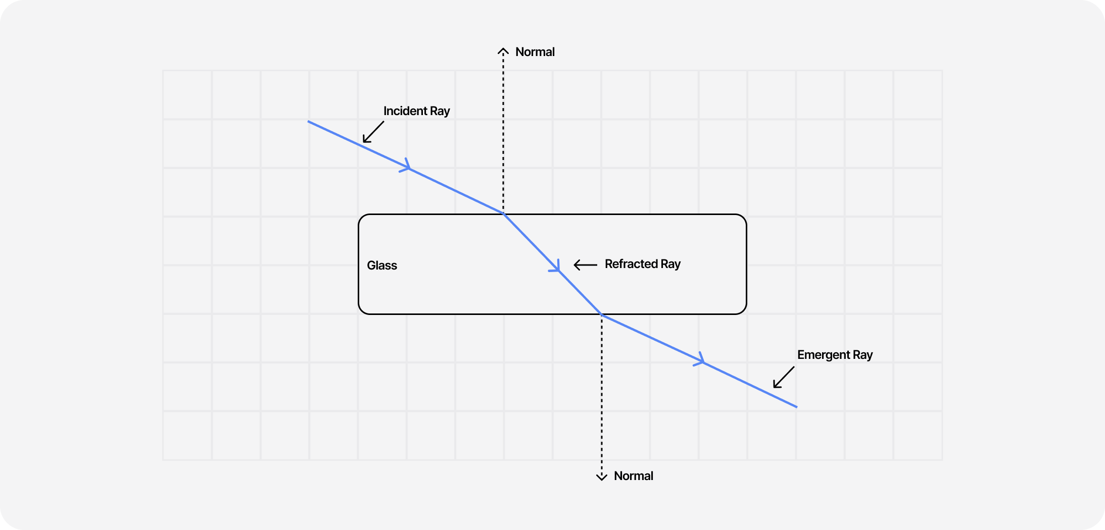
The intensity of that "bending" depends on the index of refraction (IOR) of that material. E.g. for water, that index is 1.333, and for diamond 2.42. The higher the index, the higher the "bending" effect of our refraction will appear.
When it comes to implementing it, we're in luck! GLSL has a refract function ready to use. It needs three things:
- An incident vector. In our case, it will be a vector originating from the observer (the camera) pointed toward our mesh.
- A normal vector. It represents our mesh's surface normal.
- An ior ratio.
The vertex shader of our material can help us get the first two vectors we need. The first one, which we can name eyeVector, can be obtained by normalizing the difference between the position of our mesh and the camera's.
Vertex Shader: eyeVector
1varying vec3 worldNormal;2varying vec3 eyeVector;34void main() {5vec4 worldPos = modelMatrix * vec4(position, 1.0);6vec4 mvPosition = viewMatrix * worldPos;78gl_Position = projectionMatrix * mvPosition;9eyeVector = normalize(worldPos.xyz - cameraPosition);1011//...12}
For the second one, we get it by multiplying the normal vector of the current vertex by the normalMatrix and normalizing it.
Vertex Shader: worldNormal
1varying vec3 worldNormal;2varying vec3 eyeVector;34void main() {5//...6vec3 transformedNormal = normalMatrix * normal;7worldNormal = normalize(transformedNormal);8}
Then, as we learned in The Study of Shaders with React Three Fiber, we can pass those vectors from the vertex shader using a variant to have them available in the fragment shader. We now have everything to use the refract function and calculate a refraction vector based on the ior ratio and our eyeVector.
Fragment Shader: refractVec
1//...2varying vec3 worldNormal;3varying vec3 eyeVector;45void main() {6float iorRatio = 1.0/1.31;7vec2 uv = gl_FragCoord.xy / winResolution.xy;8vec3 normal = worldNormal;9vec3 refractVec = refract(eyeVector, normal, iorRatio);1011//...12}
With that resulting vector, we can slightly shift each pixel of the texture coordinate, which gives us a relatively convincing refraction effect for our transparent material.
Fragment Shader: apply refractVec to texture
1//...2varying vec3 worldNormal;3varying vec3 eyeVector;45void main() {6float iorRatio = 1.0/1.31;7vec2 uv = gl_FragCoord.xy / winResolution.xy;8vec3 normal = worldNormal;9vec3 refractVec = refract(eyeVector, normal, iorRatio);10vec4 color = texture2D(uTexture, uv + refractVec.xy);1112gl_FragColor = color;13}
This effect is visible in the playground below 👇. I added OrbitControl to the scene so you can drag it around and see our newly built refraction in action! Try to tweak the iorRatio variable to increase/decrease the intensity of the refraction 👀!
Chromatic Dispersion
Dispersion happens when the IOR of a material varies with the wavelength of the color. As a result, the different colors composing light refract at different angles, thus making each color visible.
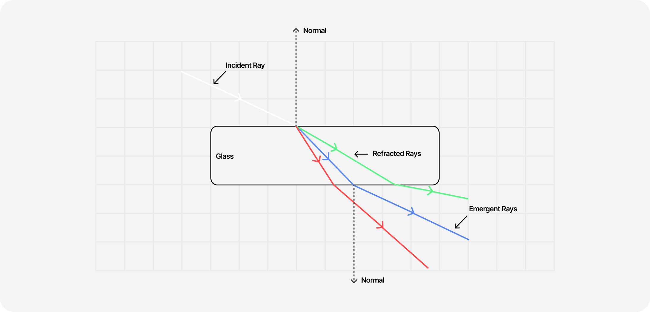
Thus, with what we learned in the previous part, we should be able to reproduce this effect by applying individual IOR values for each of the color channels (which have their own wavelength) composing the background texture.
Splitting colors with Chromatic Aberration
For this effect, one essential aspect of colors in shaders to remember is that they are always a vec4, a vector with four components: red, green, blue, and alpha, and like any vector, we can access and manipulate each of those components.
We can thus easily manipulate each value of R, G, and B by introducing a shift, thus splitting the color into its components. This effect is also sometimes called Chromatic Aberration. The widget below showcases this effect. We split the "white" color into its equivalent RGB colors:
- White has the value
vec4(1.0)orrgb(255, 255, 255) - Red has the value
vec4(1.0, 0.0, 0.0, 1.0)orrgb(255, 0, 0) - Green has the value
vec4(0.0, 1.0, 0.0, 1.0)orrgb(0, 255, 0) - Blue has the value
vec4(0.0, 0.0, 1.0, 1.0)orrgb(0, 0, 255)
You'll notice the colors red, green, and blue being more visible as the intensity of the shift increases.
We can reproduce this in our fragment shader code by:
- Introducing individual IOR for each value of R, G, and B.
- Creating unique refraction vectors for R, G, and B.
- Applying those refraction vectors for each color channel of the texture
Fragment Shader: simple dispersion
1uniform float uIorR;2uniform float uIorG;3uniform float uIorB;4//...56void main() {7float iorRatioRed = 1.0/uIorR;8float iorRatioGreen = 1.0/uIorG;9float iorRatioBlue = 1.0/uIorB;1011vec3 color = vec3(1.0);1213vec2 uv = gl_FragCoord.xy / winResolution.xy;14vec3 normal = worldNormal;1516vec3 refractVecR = refract(eyeVector, normal, iorRatioRed);17vec3 refractVecG = refract(eyeVector, normal, iorRatioGreen);18vec3 refractVecB = refract(eyeVector, normal, iorRatioBlue);1920float R = texture2D(uTexture, uv + refractVecR.xy).r;21float G = texture2D(uTexture, uv + refractVecG.xy).g;22float B = texture2D(uTexture, uv + refractVecB.xy).b;2324color.r = R;25color.g = G;26color.b = B;2728gl_FragColor = vec4(color, 1.0);29}
Thanks to those few lines of code based on the definition of the dispersion effect, we can easily reproduce it on top of our original refraction scene.
There's, however, one small problem with the look of this effect: it's not really smooth and does not feel natural 😕. Thankfully, there're a few tricks we can use as workarounds to this issue.
Additional samples for a smoother dispersion
While I was obsessing about reproducing a natural dispersion, @ore_ukonpower released https://next.junni.co.jp/ which featured a beautiful version of that effect. On top of that, it's open source! So after digging around in the code base, I learned this new technique: using "samples" to smooth out the RGB shift we introduced above.
To illustrate this technique, let's bring back the widget featuring the RGB shift effect. If we:
- iterate a certain number of times when rendering our dispersion
- introduce an extra shift for each color channel for each loop
We can obtain a better version for our effect.
As for the glsl implementation, we can achieve it by introducing a for-loop and iterating on our color shift for as many samples as we want.
Fragment Shader: smoother dispersion with samples
1uniform float uRefractPower;2uniform float uChromaticAberration;34// ...56vec3 color = vec3(0.0);78for ( int i = 0; i < LOOP; i ++ ) {9float slide = float(i) / float(LOOP) * 0.1;1011vec3 refractVecR = refract(eyeVector, normal, iorRatioRed);12vec3 refractVecG = refract(eyeVector, normal, iorRatioGreen);13vec3 refractVecB = refract(eyeVector, normal, iorRatioBlue);1415color.r += texture2D(uTexture, uv + refractVecR.xy * (uRefractPower + slide * 1.0) * uChromaticAberration).r;16color.g += texture2D(uTexture, uv + refractVecG.xy * (uRefractPower + slide * 2.0) * uChromaticAberration).g;17color.b += texture2D(uTexture, uv + refractVecB.xy * (uRefractPower + slide * 3.0) * uChromaticAberration).b;18}1920// Divide by the number of layers to normalize colors (rgb values can be worth up to the value of LOOP)21color /= float( LOOP );2223//...
In the code above, we introduced two new uniforms:
uRefractPower: which can increase/decrease the refraction effect for each sampleuChromaticAberration: which controls how intense the split between the different color channels should be
Both of these are related based on the math involved here. I simply haven't found a better formula yet to tweak one without influencing the other while preserving the desired effect.
If we enhance our dispersion code with the sampling technique we get a smooth and natural dispersion effect:
Sadly if we were to use it as such, another set of problems surfaces:
- The colors are desaturated and pale, far from the colorful renders I showed in the introduction.
- We're still limited to tweaking the red, green, and blue color channels and respective IOR.
Saturating and expanding our color space
This part focuses more on color theory and how we can leverage some of this more technical knowledge on colors to our advantage to fix those issues.
How to saturate a color in GLSL
We've all played with color saturation at some point through CSS HSLA colors or photo filters. But how can we reimplement it in GLSL? I went down that small rabbit hole, so you don't have to.
One efficient way I found to saturate a color in GLSL is to rely on the luminance or the grayscale version of that color and "mix" it with the original color. The luminance of a given color with the following formula:
L = 0.2125 * R + 0.7154 * G + 0.0721 * B
This formula can be ported to GLSL by using the dot product of 2 vectors:
- The first one is our RGB color, a
vec3. - The second one is the vector containing the coefficient of the luminance formula
vec3(0.2125, 0.7154, 0.0721).
Fragment Shader: saturation function using luminance
1vec3 sat(vec3 rgb, float intensity) {2vec3 L = vec3(0.2125, 0.7154, 0.0721);3vec3 grayscale = vec3(dot(rgb, L));45//...6}
Using GLSL's mix function we can linearly interpolate our resulting color between the grayscale version and the original color:
- an intensity value between
0and1will result in a desaturated color. - an intensity value above
1will saturate the resulting color, rendering it more intense.
Fragment Shader: full saturation function
1vec3 sat(vec3 rgb, float intensity) {2vec3 L = vec3(0.2125, 0.7154, 0.0721);3vec3 grayscale = vec3(dot(rgb, L));4return mix(grayscale, rgb, intensity);5}
We can then use this function in our fragment shader when we're building our color in our for-loop to get a more colorful result 🎨:
From RGB to rygcbv and back
In this part, I cover a trick I discovered while researching dispersion that allows us to split the RGB color space into 6 channels rygcbv (Red, Yellow, Green, Cyan, Blue, and Violet). I stumbled upon it while looking at a similar attempt to reproduce the dispersion effect in WebGL by Taylor Petrick, and they were kind enough to send me the research paper that originally introduced this technique. Thank you Taylor 🙏!
In this paper, the author, Ravishankar Sundararaman, showcases how we can obtain more color channels out of RGB by using a Fourier interpolation (see 3.2). My knowledge of Fourier series is a bit rusty 😅, so I trust them on this one. Here's the formula they propose:
I = d + e * cosθ + f * sinθ
From it, we can obtain the values of r, y, g, c, b, and v in terms of RGB. For this part, I re-did the math from scratch to demonstrate the formula they feature in the paper:
r = R/2 g = G/2 b = B/2 y = (2R + 2G - B)/6 c = (2G + 2B - R)/6 v = (2B + 2R - G)/6
[Optional] Expand to see how to obtain the formulas below from the Fourier series
With these new formulas, we can, in theory, define additional IORs to tweak the refraction intensity for these additional color channels and obtain a more detailed, tweakable dispersion effect! 🎉
There's, however, one small catch: GLSL doesn't let us directly express colors in rygcbv. So we need to go back to RGB after modifying/shifting our color channels. Luckily for us, the author also provided us with these formulas (I was sadly too tired to demonstrate them from scratch, so you'll have to trust them on this one 😅)
R = r + (2v + 2y - c)/3 G = g + (2y + 2c - v)/3 B = b + (2c + 2v - y)/3
Implementing all these formulas in GLSL is long and repetitive, so I'll let you look at and tweak the code directly from the playground below:
Finally, with these few tricks and some clever math, we managed to:
- Solve the color saturation issue from our dispersion effect 🎉
- Have additional colors and their corresponding IORs to play with 🎨
Adding volume and shininess to our dispersion
I'm not going to lie: I was very already happy with my dispersion effect when I reached this point. There were, however, a few things that were still bothering me:
- The mesh looks flat and lacks depth/volume.
- The dispersion effect from the renders I was inspired by came from the mesh themselves, whereas, in my scene, it came from background meshes.
I want to dedicate this part to how I worked around these issues by learning about and implementing more light effects and using some (maybe clever?) rendering tricks.
Specular & Diffuse light
A well-placed light and a material that interacts with it properly can do wonders for any React Three Fiber scene. For ours, we can use light to give a better sense of depth and volume to our mesh through two effects:
- Specular: simulates how light reflects on the surface of a material.
- Diffuse: simulates how light scatters on the surface of a material.
One of the simplest light models we can implement to reproduce these effects is the Blinn-Phong model.
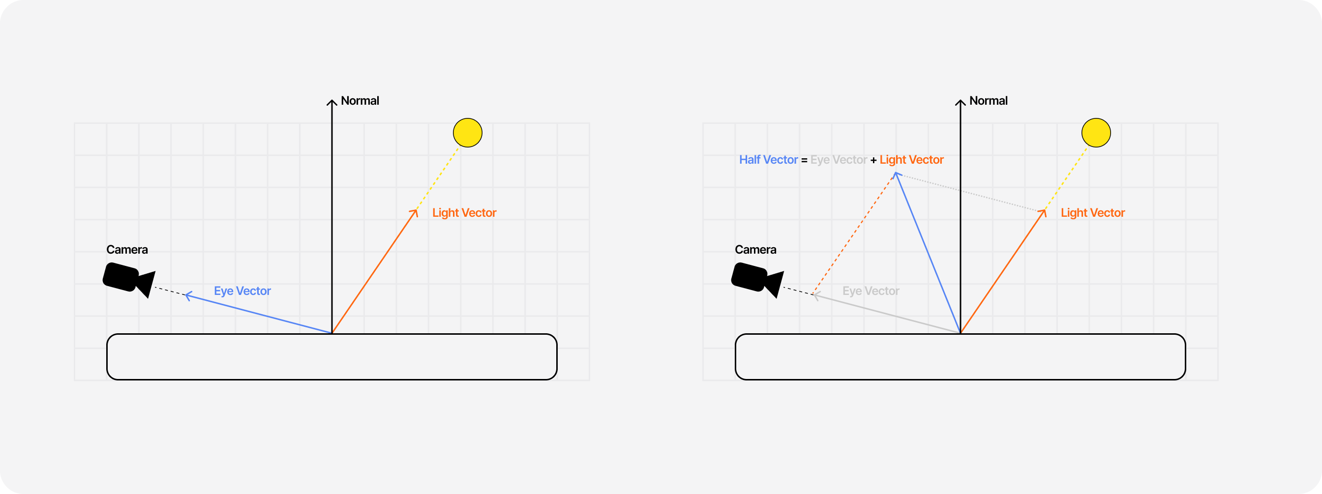
- We know the position of the viewer (eye vector) and the light source (a
vec3uniform we will nameuLight) and their respective directions. - The half-vector is obtained by adding together the light vector and eye vector.
- The dot product of the normal and the light vector gives us the diffuse value.
Which, in GLSL, translates to:
Fragment Shader: Diffuse
1//...2uniform float uShininess;3uniform float uDiffuseness;4uniform vec3 uLight;5//...67float specular(vec3 light, float shininess, float diffuseness) {8vec3 normal = worldNormal;9vec3 lightVector = normalize(-light);10vec3 halfVector = normalize(eyeVector + lightVector);1112float NdotL = dot(normal, lightVector);13float kDiffuse = max(0.0, NdotL);14//...15}16//...
For the specular, we can get it through the dot product of the normal and the half-vector, then using that value to the power of the "shininess" of the material (we can pass this value as a uShininess uniform as well).
Fragment Shader: Specular and Diffuse
1//...2uniform float uShininess;3uniform float uDiffuseness;4uniform vec3 uLight;5//...67float specular(vec3 light, float shininess, float diffuseness) {8vec3 normal = worldNormal;9vec3 lightVector = normalize(-light);10vec3 halfVector = normalize(eyeVector + lightVector);1112float NdotL = dot(normal, lightVector);13float NdotH = dot(normal, halfVector);14float NdotH2 = NdotH * NdotH;1516float kDiffuse = max(0.0, NdotL);17float kSpecular = pow(NdotH2, shininess);1819return kSpecular + kDiffuse * diffuseness;20}21//...
I found, however, that I could achieve a better specular by raising the dot product of the normal and the half-vector to the power of 2. I can't find exactly where I saw this formula, but I'd love to know your thoughts if you've ever encountered it.
After combining specular and diffuse, our mesh now interacts with (an arbitrarily well-positioned) light, which results in a beautiful, more realistic render ✨.
Reflection with the Fresnel effect
When we look at an object, the amount of light reflected by that object may vary in function of the viewing angle. You can observe this effect in real life when looking at a window for instance:
- when viewed at an angle, it reflects more light.
- when looked at standing in front of it, it's see-through and reflects little light.
This reflection effect is called the Fresnel effect, and it's one of those effects that can seem subtle but can go long ways to make your material reflect the ambient light more realistically. And it's no different for our dispersion scene!
I'm not going to detail more about the physics of the Fresnel effect, as there are many articles out there that already did it way better than I could do (plus, this blog post would be a bit too long):
The GLSL implementation of this effect can be found in many shader related projects, as it's a pretty popular effect to add to many materials. For this project, I used the following:
Fragment Shader: Fresnel
1//...2uniform float uFresnelPower;3//...45float fresnel(vec3 eyeVector, vec3 worldNormal, float power) {6float fresnelFactor = abs(dot(eyeVector, worldNormal));7float inversefresnelFactor = 1.0 - fresnelFactor;89return pow(inversefresnelFactor, power);10}
Which, once added to our scenes, gives us a nice glow on the outskirts of our mesh:
Backside rendering
This last part is dedicated to an accidental trick I found while tinkering with this scene, which I later found out was actually featured in an article titled Real-time Multiside Refraction in Three Steps.
My train of thought went as follows:
- Our mesh is transparent
- We should see through the mesh, thus the background and the rest of the scene
- But we should also see the "inside" of the mesh itself, i.e. it's backside!
Thus I attempted to render the backside of the mesh and then render the frontside, both with the same material and its light effects and dispersion properties. This led to some pretty sweet results bringing me closer to a realistic dispersion effect 🎉.
How does to do so? Here's a diagram that shows you how we can do that in our render loop:
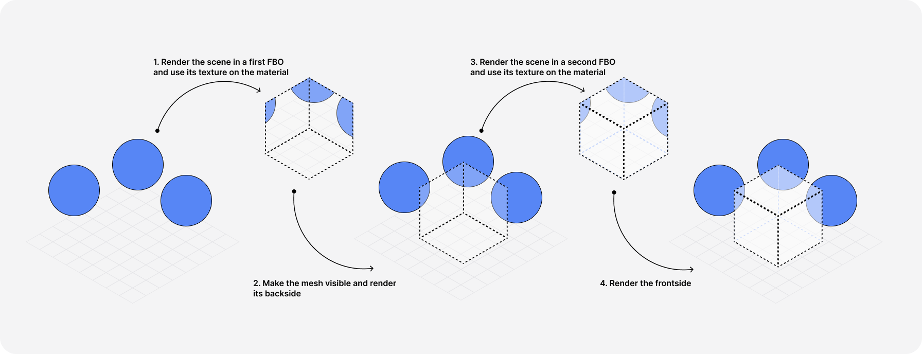
With a few lines of code, we can add these steps to the useFrame hook and collocate them with the code we wrote in the first part to make our mesh transparent.
Excerpt of a R3F scene that renders the backside and frontside of a mesh through FBOs
1//...2const Dispersion = () => {3const mesh = useRef();4const mainRenderTarget = useFBO();5const backRenderTarget = useFBO();67//...89useFrame((state) => {10const { gl, scene, camera } = state;11// Hide the mesh12mesh.current.visible = false;1314//...1516gl.setRenderTarget(backRenderTarget);17// Render the scene into the "back" FBO18gl.render(scene, camera);1920// Pass the FBO texture to the material21mesh.current.material.uniforms.uTexture.value = backRenderTarget.texture;22// Render the backside and display the mesh23mesh.current.material.side = THREE.BackSide;24mesh.current.visible = true;2526gl.setRenderTarget(mainRenderTarget);27// Render the scene into the "front" FBO28gl.render(scene, camera);2930// Pass the FBO texture to the material31mesh.current.material.uniforms.uTexture.value = mainRenderTarget.texture;32// Render the frontside33mesh.current.material.side = THREE.FrontSide;3435gl.setRenderTarget(null);36});37};38//...
And just like that, something pretty incredible happens through this trick:
- The back side has its own light effects, specular, Fresnel, and diffuse.
- It also refracts and disperses the rest of the scene, just like we've seen throughout this article.
But once we add the front side on top of that with the same material:
- The specular of the back side is both refracted and dispersed by the front side thus creating a beautiful dispersion that's pretty convincing 🎉
- The same applies to the other light effects ✨
- The dispersion effect changes with the viewing angle as it would in real life.
Add to that some tweaks to the position of the camera and you get this stunning result ⭐:
Conclusion
We now have a mesh that achieves a beautiful and somewhat realistic dispersion effect in real time that can be tweaked to your liking through its many inputs/uniforms 🎉. This project was quite fun (and long) and I learned a lot. The result is perhaps not as beautiful/colorful as the one from the renders, but the effect is pretty close to what I wanted to achieve! I hope this article will inspire you to implement some shader light effects into your own projects ✨.
While we tried to have a "physically grounded" implementation of this effect, we had to deviate a bit to guarantee that the result would still look good with some tricks. I could have probably done better there, but I was reaching the limits of my shader knowledge.
Another aspect I wish I could improve upon would be performance: using a for loop in my shader is probably a questionable choice, and the fps can drop a lot the higher the sample number is. That will be the first thing I'll try to improve when I deep-dive into this material again in the future (I need some rest / do other things now). Of course, do not hesitate to reach out if you have ideas on how we could further improve this shader. I'll make sure to include your suggestions in this article 😄.