On Shaping Light
As I became more familiar with post-processing over the past few months, I was curious to push those newly learned techniques beyond pure stylization to achieve something more functional. I wanted to find new ways to enrich my 3D work which wouldn't be possible without leveraging effects and passes alongside custom shaders.
As it turns out, post-processing is great entrypoint to enhance a 3D scene with atmospheric and lighting effects, allowing for more realistic and dramatic visuals. Because these effects operate in screen space, their performance cost is decoupled from the underlying scene's complexity, making them an efficient solution for balancing performance and visual quality. At the end of the day, when we work with effects, we are still just drawing pixels on a screen.
Among those effects, Volumetric Lighting was the first one to catch my attention as I always wanted to create those beautiful beams of light, shining through trees or buildings, creating a dreamy and atmospheric vibe to my work (heavily featured in "Clair Obscur: Expedition 33" which I've been playing a lot recently for "research purposes"). On top of that, I found out that these light effects can be made possible with Volumetric Raymarching, a topic I've covered in the past but haven't found any practical application in my React Three Fiber work so far!
Thus, by combining these two seemingly unrelated pieces, that are post-processing and raymarching, in the context of volumetric lighting, I discovered a new set of tricks to complement my shader work, enhance the visual of my scenes, and, more importantly, share with you. In this article, I'll showcase not only what makes a good volumetric lighting effect using raymarching, but also detail every technique behind it, such as coordinate space transformations, shadow mapping, and new usage of depth buffers, as well as further expansions into multi-directional lighting and multi-light examples.
As someone whose only experience with post-processing was for stylization purposes, leveraging it alongside volumetric raymarching, which I studied in depth separately, was enticing. The resulting combination would allow one to paint arbitrary light effects onto a scene based on the camera's position, the source of the light, and all of that while taking into account the many objects that could compose the scene.
However, there was still a clear divide that made the result feel unreachable at first: raymarching operates in a three-dimensional space, while post-processing lives in screen space, which is two-dimensional. Thus, before diving into anything related to volumetric lighting proper, we should first learn about the process allowing us to jump from one to the other: coordinate system transformations.
Coordinate systems and transformations
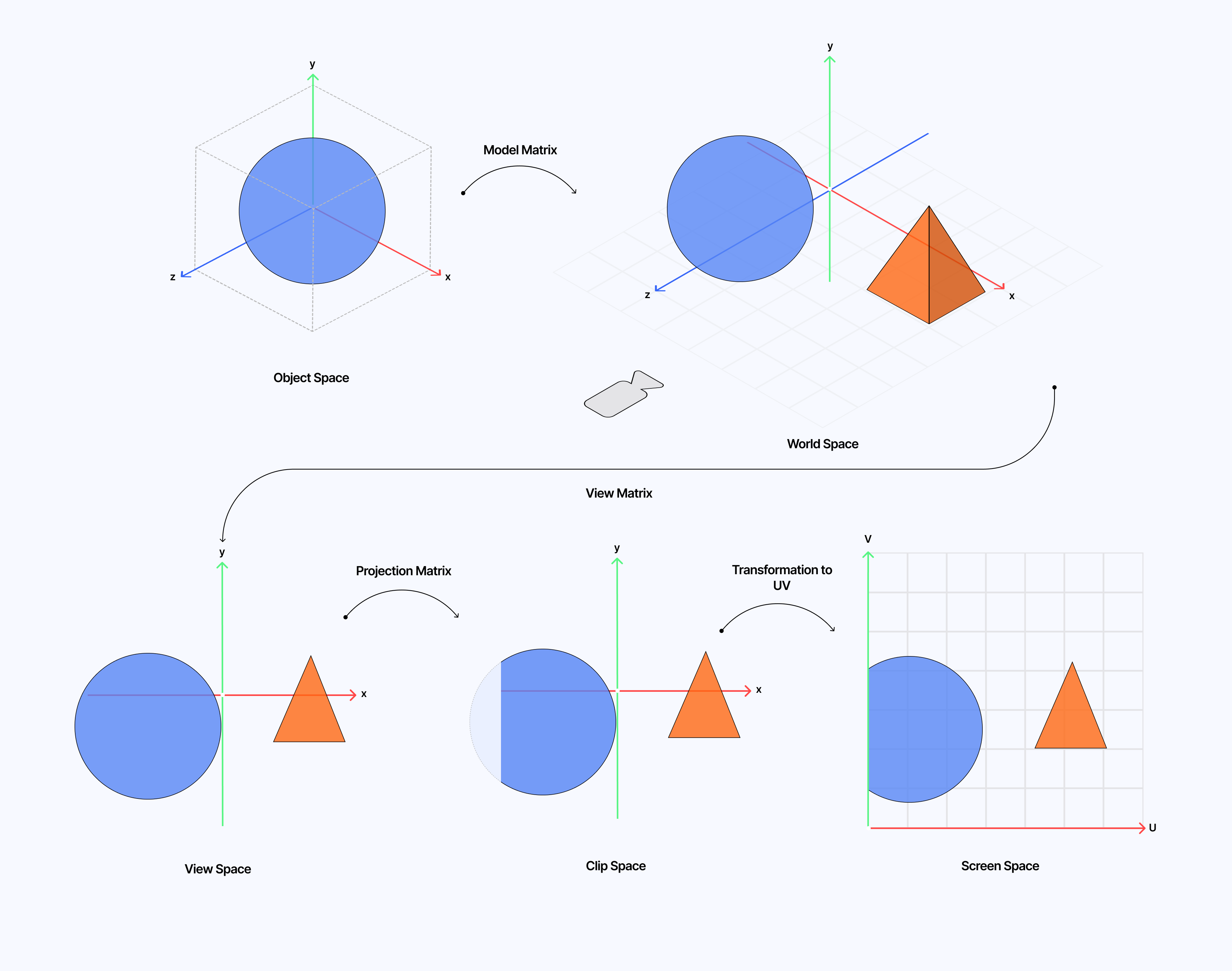
3D scenes operate across several coordinate systems that each have a specific role:
- Object/Model space: where coordinates are relative to the object's origin.
- World space: the shared coordinate system between all objects on the scene.
- View space: where coordinates are relative to the camera. The camera is at (0, 0, 0) looking down the z-axis by default.
- Clip space: where coordinates are still related to the camera but transformed to perform "clipping".
- NDC - Normalized Device Coordinates: the normalized version of the clip space coordinate system 1.
- Screen-space: the final 2D coordinate system of the rendered image: the frame buffer.
To help you visualize them, the diagram below illustrates each coordinate system defined above.
Given that our volumetric lighting work will start in screen space, due to relying on post-processing, we'll need to reconstruct 3D rays from our camera through each pixel of our effect by converting screen space coordinates into world space coordinates. We can achieve this with the following formulas:
xNDC = uv.x * 2.0 - 1.0
yNDC = uv.y * 2.0 - 1.0
zNDC = depth * 2.0 - 1.0
clipSpace = { x: xNDC, y: yNDC, z: zNDC, 1.0 }
worldSpace = viewMatrixInverse * projectionMatrixInverse * clipSpace
worldSpace /= worldSpace.w
where uv is the UV coordinate of the current fragment of our volumetric lighting post-processing pass and depth, is the depth texture of the underlying scene sampled at that same UV.
From it, we can derive the GLSL function that we will use in later examples:
getWorldPosition function
1vec3 getWorldPosition(vec2 uv, float depth) {2float clipZ = depth * 2.0 - 1.0;3vec2 ndc = uv * 2.0 - 1.0;4vec4 clip = vec4(ndc, clipZ, 1.0);56vec4 view = projectionMatrixInverse * clip;7vec4 world = viewMatrixInverse * view;89return world.xyz / world.w;10}
Our first light ray
Now that we know the concept of coordinate systems and how to jump from screen space (post-processing pass) to world space (3D space), we can start working towards drawing our first raymarched light. To do so, we can start putting together a simple scene with a VolumetricLighting effect that can take the following arguments:
cameraFar: the depth limit beyond which nothing will be visible or rendered.projectionMatrixInverse: thecamera.projectionMatrixInverseproperty that we'll use to convert our coordinates from clip-space to view-space.viewMatrixInverse, which we will set as thecamera.matrixWorldproperty, the matrix that transforms coordinates from view space to world space.cameraPosition: the position of our camera from which our raymarching will start.lightDirection: a normalized vector representing the direction the light points toward.lightPosition: a vector 3 representing the position of our light.coneAngle, which represents how wide our spotlight aperture is.
These properties are all we need to render a simple volumetric raymarched light shaped like a cone, originating from a given point and pointing in an arbitrary direction.
Another essential property from our scene that we will need to make this setup work is the depth buffer. You may have noticed it mentioned in the part on the coordinate system, but it is missing from the set of properties above. That is because we luckily get it for free through postprocessing's Effect class by passing the EffectAttribute.DEPTH in the effect's constructor:
Volumetric Lighting effect class
1class VolumetricLightingEffectImpl extends Effect {2constructor(3cameraFar = 500,4projectionMatrixInverse = new THREE.Matrix4(),5viewMatrixInverse = new THREE.Matrix4(),6cameraPosition = new THREE.Vector3(),7lightDirection = new THREE.Vector3(),8lightPosition = new THREE.Vector3(),9coneAngle = 40.010) {11const uniforms = new Map([12['cameraFar', new THREE.Uniform(cameraFar)],13['projectionMatrixInverse', new THREE.Uniform(projectionMatrixInverse)],14['viewMatrixInverse', new THREE.Uniform(viewMatrixInverse)],15['cameraPosition', new THREE.Uniform(cameraPosition)],16['lightDirection', new THREE.Uniform(lightDirection)],17['lightPosition', new THREE.Uniform(lightPosition)],18['coneAngle', new THREE.Uniform(coneAngle)],19]);2021super('VolumetricLightingEffect', fragmentShader, {22attributes: EffectAttribute.DEPTH,23uniforms,24});2526this.uniforms = uniforms;27}2829update(_renderer, _inputBuffer, _deltaTime) {30this.uniforms.get('projectionMatrixInverse').value =31this.projectionMatrixInverse;32this.uniforms.get('viewMatrixInverse').value = this.viewMatrixInverse;33this.uniforms.get('cameraPosition').value = this.cameraPosition;34this.uniforms.get('cameraFar').value = this.cameraFar;35this.uniforms.get('lightDirection').value = this.lightDirection;36this.uniforms.get('lightPosition').value = this.lightPosition;37this.uniforms.get('coneAngle').value = this.coneAngle;38}39}
That exposes the depth texture via a built-in uniform depthBuffer in our fragment shader code 2
With that out of the way, we can start putting together our raymarched light by proceeding as follows:
- We sample the depth buffer at a given
uvin screen space since those UVs represent the coordinates of our effect. - We reconstruct the 3D position in world space for that pixel using the
getWorldPositionfunction we defined in the first part.
1void mainImage(const in vec4 inputColor, const in vec2 uv, out vec4 outputColor) {2float depth = readDepth(depthBuffer, uv);3vec3 worldPosition = getWorldPosition(uv, depth);45//...6}
- We set the
rayOriginto our camera's position. - We define the direction of that ray as a vector pointing from the camera toward the current pixel in world space.
- We also set our
lightPosition(in world space) andlightDirectionvectors.
1vec3 rayOrigin = cameraPosition;2vec3 rayDir = normalize(worldPosition - rayOrigin);34vec3 lightPos = lightPosition;5vec3 lightDir = normalize(lightDirection);
- We then raymarch our light using a classic volumetric raymarching loop that accumulates density/light as we march alongside our ray. We also make sure to attenuate the light as the distance between the source of the light and the current raymarched position increases.
1float coneAngleRad = radians(coneAngle);2float halfConeAngleRad = coneAngleRad * 0.5;34float fogAmount = 0.0;5float lightIntensity = 1.0;6float t = STEP_SIZE;78for (int i = 0; i < NUM_STEPS; i++) {9vec3 samplePos = rayOrigin + rayDir * t;1011if (t > cameraFar) {12break;13}1415vec3 toSample = normalize(samplePos - lightPos);16float cosAngle = dot(toSample, lightDir);1718if (cosAngle < cos(halfConeAngleRad)) {19t += STEP_SIZE;20continue;21}2223float distanceToLight = length(samplePos - lightPos);24float attenuation = exp(-0.05 * distanceToLight); // could be 1.0 / distanceToLight2526fogAmount += attenuation * lightIntensity;2728t += STEP_SIZE;29}
- We finally combine the obtained accumulation of light with the
inputColorof our effect and return it as the color output of our fragment shader.
Everything we detailed so far is present in the demo below, which sets up the foundation for the examples we'll see later in this article. In it you'll find:
- A simple React Three Fiber scene.
- Our
VolumetricLightingEffecteffect and its definition. - Our effect's fragment shader.
We now have a simple ray of light, built using volumetric raymarching, overlayed on top of a pre-existing scene using post-processing. You can try to move the light position (world space) and see the proper set of pixels drawn in screen space.
Depth-based stopping
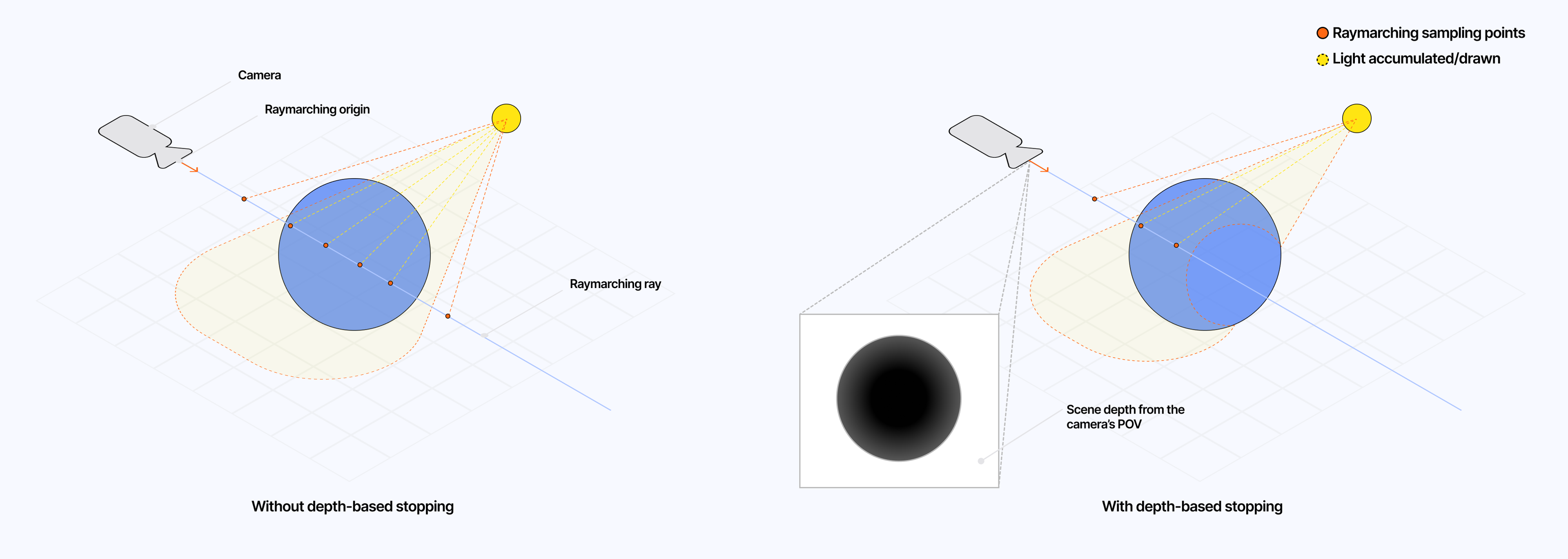
When raymarching, we draw our light onto our scene without any constraints. The ray continues marching beyond what the camera/the viewer can see. We thus end up with light or other atmospheric effects such as fog visible through walls or objects, which not only breaks the realism of our effect but also wastes performance because we run our intensive raymarching process beyond where it should have stopped in the first place.
By leveraging our depth texture, which we sampled in screen space, and reconstructing the point in world space, we can calculate the distance between our camera and the current fragment point in world space to stop our raymarching earlier whenever we start sampling beyond the scene's depth:
Implementing depth-based stopping in our raymarching loop
1void mainImage(const in vec4 inputColor, const in vec2 uv, out vec4 outputColor) {2float depth = readDepth(depthBuffer, uv);3vec3 worldPosition = getWorldPosition(uv, depth);45float sceneDepth = length(worldPosition - cameraPosition);67//...89for (int i = 0; i < NUM_STEPS; i++) {10vec3 samplePos = rayOrigin + rayDir * t;1112if (t > sceneDepth || t > cameraFar) {13break;14}15// ...16}17// ...18}
Adding it to our previous demo fixes the issue where the light source could be seen through the sphere when moving the camera around in the scene.
Shaping our light ray
We now have a robust first pass at volumetric lighting. While we did give it somewhat of a shape from the get-go in the first example, I still wanted to dedicate a small chunk of this article to showing you a few tricks for shaping your volumetric light in any way you want.
My friend @KennyPirman does this wonderfully well in his habitat demo scene project, a 3D reconstruction of an O’Neil cylindrical world floating in space.
In it, he shapes the volumetric light/fog and other atmospheric effects as a cylinder using its corresponding Signed Distance Function to fit his specific use case, and we can do the same in our example:
Using SDFs to shape our raymarched light
1float sdCylinder(vec3 p, vec3 axisOrigin, vec3 axisDir, float radius) {2vec3 p_to_origin = p - axisOrigin;3float projectionLength = dot(p_to_origin, axisDir);4vec3 closestPointOnAxis = axisOrigin + axisDir * projectionLength;5float distanceToAxis = length(p - closestPointOnAxis);6return distanceToAxis - radius;7}89float smoothEdgeWidth = 0.1;1011void mainImage(const in vec4 inputColor, const in vec2 uv, out vec4 outputColor) {12// ...13for (int i = 0; i < NUM_STEPS; i++) {14vec3 samplePos = rayOrigin + rayDir * t;1516if (t > sceneDepth || t > cameraFar) {17break;18}1920float sdfVal = sdCylinder(samplePos, lightPos, lightDir, 2.0);21float shapeFactor = smoothstep(0.0, -smoothEdgeWidth, sdfVal);2223if (shapeFactor < 0.1) {24t += STEP_SIZE;25continue;26}2728// ...29}30}
We can leverage any SDF in our toolset 3, the same ones that we explored in my Raymarching blog post 2 years ago, to shape our light as we see fit. The demo below showcases a few examples of lights shaped like cones, spheres, cylinders, and toruses.
Having established the foundation of our volumetric lighting effect, we can now dive into the more complex aspect of this article: computing shadows. In this part, you will see how to:
- Leverage once again coordinate systems, however, this time, to go from world space back to screen space.
- Create a shadow map of our scene.
- Use both concepts to stop drawing our light when occluded by objects in the scene.
Creating a shadow map of our scene
Our current implementation of volumetric lighting does not take the shadows cast by objects placed in the way of our light into account. Realistically, we should see dark streaks or bands where the light is occluded. Moreover, akin to depth-based stopping, the lack of shadow handling results in useless operations: we draw volumetric light where no light should be present.
The diagram below illustrates what we have now compared to what we should expect from an accurate volumetric light:
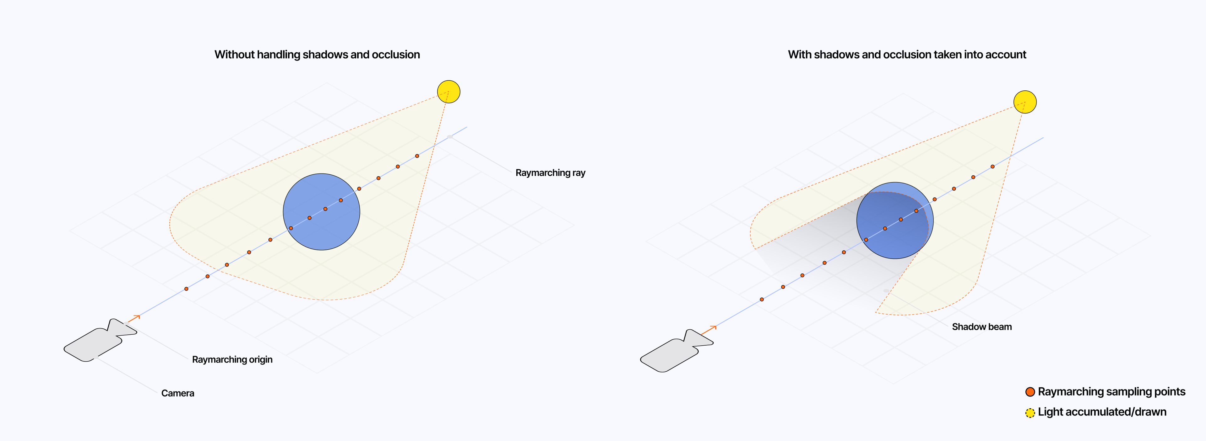
To solve this, we will need to generate a shadow map of our scene: a texture representing the depth of the scene from the point of view of our light. We can achieve this by leveraging the same trick we used for caustics 4 back in early 2024 to extract the normals of our object:
- We create a dedicated render target for our shadows
- We create a dedicated virtual camera and place it in the same position as our light.
- We render the scene using this camera.
Since we need the depth of our scene, we need to use Three.js DepthTexture and the depth option set to true when creating our render target. We should also assign a resolution to the resulting depth texture. By default, I chose 256 x 256; remember that the bigger the shadow map, the more intensive our raymarching loop will be.
For our light camera, we need to adjust its field of view or fov attribute accordingly. In our case, we can base its value on the coneAngle or radius of our volumetric light, depending on whether you are respectively using a conal or cylindrical-shaped light.
Setting up our light camera and shadow FBO
1// ...23const lightCamera = useMemo(() => {4const cam = new THREE.PerspectiveCamera(90, 1.0, 0.1, 100);5cam.fov = coneAngle;6return cam;7}, [coneAngle]);89const shadowFBO = useFBO(shadowMapSize, shadowMapSize, {10depth: true,11depthTexture: new THREE.DepthTexture(12shadowMapSize,13shadowMapSize,14THREE.FloatType15),16});1718const lightPosition = useRef(new THREE.Vector3(4.0, 4.0, -4.0));19const lightDirection = useRef(20new THREE.Vector3().copy(lightPosition.current).negate().normalize()21);2223useFrame((state) => {24const { gl, camera, scene, clock } = state;2526lightCamera.position.copy(lightPosition.current);27lightCamera.updateMatrixWorld();28lightCamera.updateProjectionMatrix();2930const currentRenderTarget = gl.getRenderTarget();3132gl.setRenderTarget(shadowFBO);33gl.clear(false, true, false);34gl.render(scene, lightCamera);3536gl.setRenderTarget(currentRenderTarget);37gl.render(scene, camera);3839// ...40});4142// ...
With this valuable depth data in our hands, we can leverage it within our raymarching loop and stop it from drawing pixels whenever our light gets occluded.
Calculating shadows and occlusion
In this section, we will go through the implementation of a function calculateShadow that, given a certain point in world space, returns:
1.0if the point is not in shadow0.0if the point is in shadow
To achieve that result, we first need to take that point and transform its coordinates back to screen space using the projection and view matrices of the lightCamera we just created.
Transforming the current sampled point to screen space
1uniform sampler2D shadowMap;2uniform mat4 lightViewMatrix;3uniform mat4 lightProjectionMatrix;4uniform float shadowBias;56float calculateShadow(vec3 worldPosition) {7vec4 lightClipPos = lightProjectionMatrix * lightViewMatrix * vec4(worldPosition, 1.0);8vec3 lightNDC = lightClipPos.xyz / lightClipPos.w;910vec2 shadowCoord = lightNDC.xy * 0.5 + 0.5;11float lightDepth = lightNDC.z * 0.5 + 0.5;1213// ...1415}
We can see in the code snippet above that this process is simply the reverse of what we did for our first light ray. Here:
shadowCoordrepresents theuvcoordinates we will use to sample from ourshadowMaptexture.lightDepthrepresents the depth of the current pixel from the point of view of ourlightCamera.
With those coordinates established, we can first handle some edge cases: if the point is outside of the lightCamera's frustum, we will consider the point as lit, whether it falls outside of a valid UV coordinate range or lies beyond the camera's far plane.
Detecting occlusion - Edge cases
1float calculateShadow(vec3 worldPosition) {2vec4 lightClipPos = lightProjectionMatrix * lightViewMatrix * vec4(worldPosition, 1.0);3vec3 lightNDC = lightClipPos.xyz / lightClipPos.w;45vec2 shadowCoord = lightNDC.xy * 0.5 + 0.5;6float lightDepth = lightNDC.z * 0.5 + 0.5;78if (9shadowCoord.x < 0.0 ||10shadowCoord.x > 1.0 ||11shadowCoord.y < 0.0 ||12shadowCoord.y > 1.0 ||13lightDepth > 1.014) {15return 1.0;16}1718// ...1920}
We can now focus on the core of the shadow logic. First, we need to sample the shadowMap using the UV coordinates defined via shadowCoord. The resulting color represents the depth of the closest surface visible from the point of view of the lightCamera at that given pixel. Given that it is a grayscale texture, we can consider a single color channel and compare it to the lightDepth:
- If the
lightDepthat that given pixel is larger than theshadowMapDepth, the point is in shadow. - Else, the point is not in shadow.
Detecting occlusion
1float calculateShadow(vec3 worldPosition) {2vec4 lightClipPos = lightProjectionMatrix * lightViewMatrix * vec4(worldPosition, 1.0);3vec3 lightNDC = lightClipPos.xyz / lightClipPos.w;45vec2 shadowCoord = lightNDC.xy * 0.5 + 0.5;6float lightDepth = lightNDC.z * 0.5 + 0.5;78if (9shadowCoord.x < 0.0 ||10shadowCoord.x > 1.0 ||11shadowCoord.y < 0.0 ||12shadowCoord.y > 1.0 ||13lightDepth > 1.014) {15return 1.0;16}1718float shadowMapDepth = texture2D(shadowMap, shadowCoord).x;1920if (lightDepth > shadowMapDepth + shadowBias) {21return 0.0;22}2324return 1.0;25}
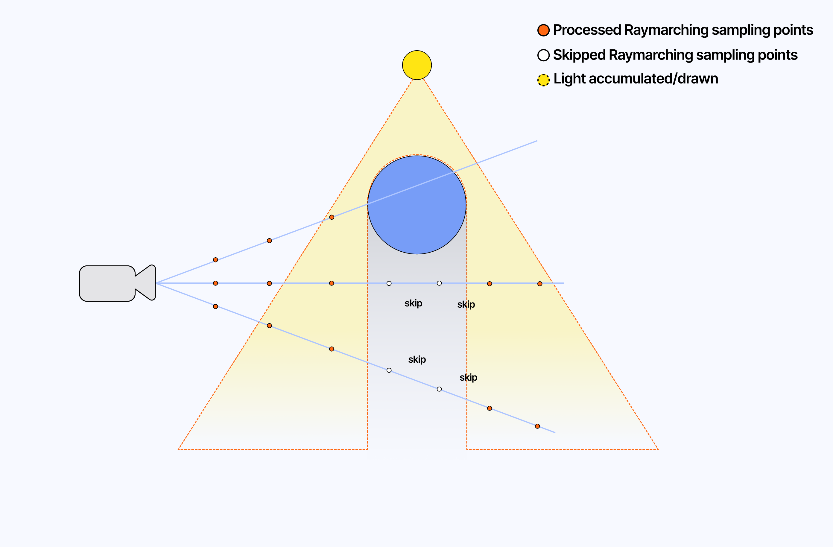
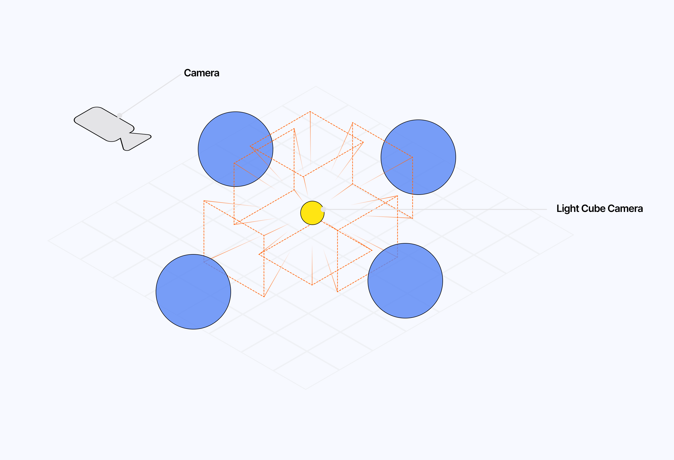
The diagram below illustrates the specific aspects and edge cases of our current setup.
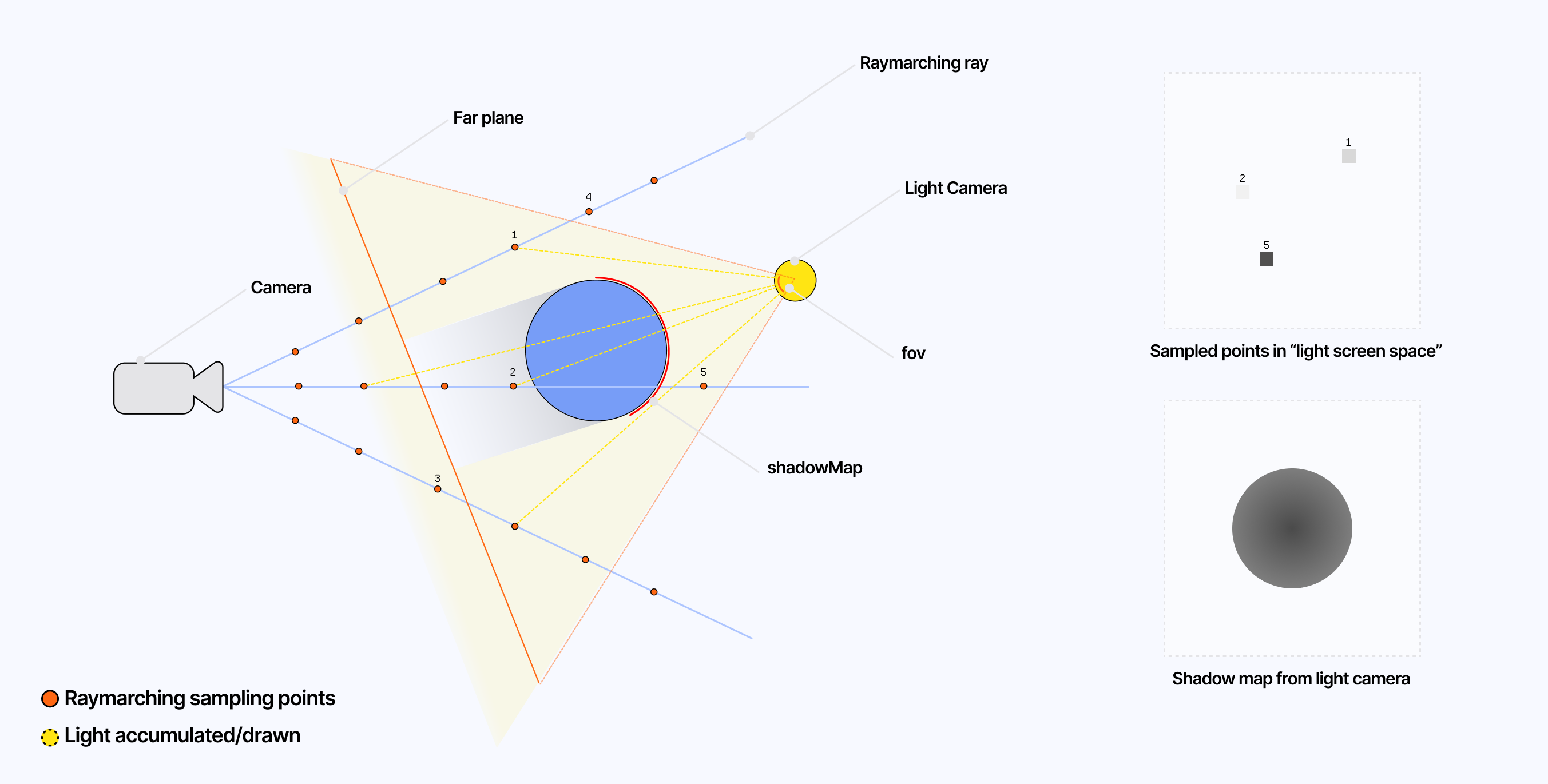
You can visualize what our lightCamera sees by outputting the result of this function and returning it as the final color of our effect:
1float shadow = calculateShadow(worldPosition);23outputColor = vec4(vec3(shadow), 1.0);
Once defined, we can leverage this function as a skip condition in our raymarching loop. Why a skip? Because points beyond the current sampled point in shadow may not be occluded. Thus, we keep marching our ray and sampling in case we need to accumulate more light later on.
Taking shadows into account while raymarching
1// ...2for (int i = 0; i < NUM_STEPS; i++) {3vec3 samplePos = rayOrigin + rayDir * t;45if (t > sceneDepth || t > cameraFar) {6break;7}89float shadowFactor = calculateShadow(samplePos);10if (shadowFactor == 0.0) {11t += STEP_SIZE;12continue;13}1415// ...16t += STEP_SIZE17}1819// ...
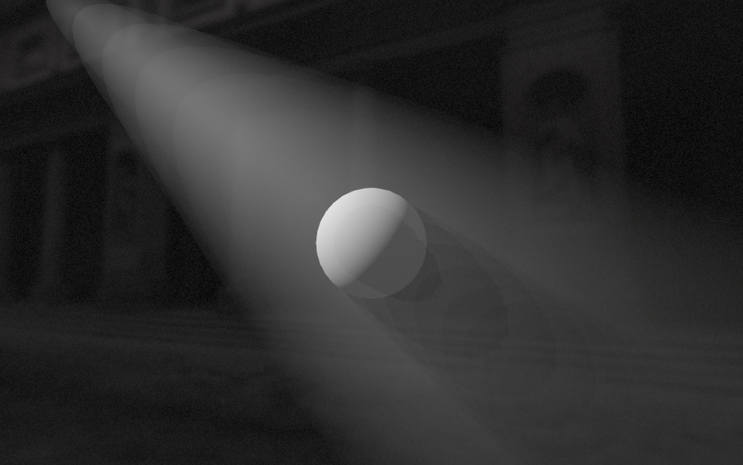
Once integrated into our original demo, we can observe some beautiful shadow beams as a result of the volumetric light being blocked by our sphere.
We now have all the building blocks for a beautiful volumetric light effect: a shaped light accumulating through a volume with shadow beams appearing when occluded. It is time to add the little details and improvements to our post-processing shader that will not only make our light appear more realistic but also more performant.
Phase function and noise
Currently, our light has the following attenuation function:
float attenuation = exp(-0.05 * distanceTofLight);. While this distance-based attenuation helped us get started, there are better ways to simulate light propagating through a volume.
First, we can introduce directional scattering using the Henyey-Greenstein function. I covered this function in lengths in Real-time dreamy Cloudscapes with Volumetric Raymarching when attempting to improve the way light gets accumulated within raymarched clouds. The function has the same purpose here. It will help us yield more realistic lighting throughout our volume:
Henyey-Greenstein phase function
1float HGPhase(float mu) {2float g = SCATTERING_ANISO;3float gg = g * g;45float denom = 1.0 + gg - 2.0 * g * mu;6denom = max(denom, 0.0001);789float scatter = (1.0 - gg) / pow(denom, 1.5);10return scatter;11}
We can include the result of the phase function when computing the luminance / light contribution of the current step in our raymarching loop.
Luminance
1// ...23for (int i = 0; i < NUM_STEPS; i++) {4vec3 samplePos = rayOrigin + rayDir * t;5// Stop sampling when camera far or scene depth is reached6if (t > sceneDepth || t > cameraFar) {7break;8}910// Handling shadows/occlusion11float shadowFactor = calculateShadow(samplePos);12if (shadowFactor == 0.0) {13t += STEP_SIZE;14continue;15}1617// Shaping the light via SDF18float sdfVal = sdCone(samplePos, lightPos, lightDir, halfConeAngleRad);19float shapeFactor = smoothstep(0.0, -smoothEdgeWidth, sdfVal);2021if (shapeFactor < 0.1) {22t += STEP_SIZE;23continue;24}2526float distanceToLight = length(samplePos - lightPos);27vec3 sampleLightDir = normalize(samplePos - lightPos);2829float attenuation = exp(-0.3 * distanceToLight);30float scatterPhase = HGPhase(dot(rayDir, -sampleLightDir));31vec3 luminance = lightColor * LIGHT_INTENSITY * attenuation * scatterPhase;3233// ...34t += STEP_SIZE35}3637// ...
The next step is to tweak how much light gets scattered through:
stepDensity: a variable that simulates the amount of fogstepTransmittance: a variable that represents the amount of light that gets absorbed by the medium/fog using Beers' Law.
Accumulated light
1// ...2void mainImage(const in vec4 inputColor, const in vec2 uv, out vec4 outputColor) {3// ...45float transmittance = 5.0;6vec3 accumulatedLight = vec3(0.0);78for (int i = 0; i < NUM_STEPS; i++) {9// ...1011float distanceToLight = length(samplePos - lightPos);12vec3 sampleLightDir = normalize(samplePos - lightPos);1314float attenuation = exp(-0.3 * distanceToLight);15float scatterPhase = HGPhase(dot(rayDir, -sampleLightDir));16vec3 luminance = lightColor * LIGHT_INTENSITY * attenuation * scatterPhase;1718float stepDensity = FOG_DENSITY * shapeFactor;19stepDensity = max(stepDensity, 0.0);2021float stepTransmittance = BeersLaw(stepDensity * STEP_SIZE, 1.0);22transmittance *= stepTransmittance;23accumulatedLight += luminance * transmittance * stepDensity * STEP_SIZE;2425t += STEP_SIZE;26}2728vec3 finalColor = inputColor.rgb + accumulatedLight;2930outputColor = vec4(finalColor, 1.0);31}
With this, we now have a more realistic light propagating through a medium with consistent density. The demo below combines the code we just covered into our original scene:
Of course, to yield a more moody result, we could opt for a more dynamic and organic medium for our light to propagate through, like a thicker fog of soft clouds. To do so, we can add some Fractal Brownian Motion, which I introduced in both my raymarching and volumetric raymarching posts, allowing us to render complex noise patterns that mimic the variations of density we can find in those atmospheric effects.
Adding fog-like noise to our effect
1// ...23const float NOISE_FREQUENCY = 0.5;4const float NOISE_AMPLITUDE = 10.0;5const int NOISE_OCTAVES = 3;67float fbm(vec3 p) {8vec3 q = p + time * 0.5 * vec3(1.0, -0.2, -1.0);9float g = noise(q);1011float f = 0.0;12float scale = NOISE_FREQUENCY;13float factor = NOISE_AMPLITUDE;1415for (int i = 0; i < NOISE_OCTAVES; i++) {16f += scale * noise(q);17q *= factor;18factor += 0.21;19scale *= 0.5;20}2122return f;23}2425void mainImage(const in vec4 inputColor, const in vec2 uv, out vec4 outputColor) {26// ...27for (int i = 0; i < NUM_STEPS; i++) {28// ...2930// Shaping the light via SDF31float sdfVal = sdCone(samplePos, lightPos, lightDir, halfConeAngleRad);32float shapeFactor = -sdfVal + fbm(samplePos); // you can also name this "density"3334if (shapeFactor < 0.1) {35t += STEP_SIZE;36continue;37}3839//...40}41// ...42}4344// ...
The demo below integrates this small yet essential add-on to our volumetric lighting effect, giving the impression of a powerful beam of light cutting through thick fog.
Performance improvements
As with many of my raymarching experiments, the main performance issues often come from the granularity of the raymarching loop, specifically the size of each step. In our current setup, each step of the loop triggers several heavy processes such as sampling textures until we reach the maximum amount of steps. To alleviate that, we could:
- Reduce the maximum number of steps, but this would lead to stopping sampling light too early and ending with less depth in our volumetric light.
- Increase the step size to reach the maximum amount of steps quicker, however, this would lead to visible banding and the quality of the output would decrease.
To work around those artifacts while reducing the performance impact of our raymarching loop, we can introduce some blue noise dithering. I briefly mentioned this technique in my article on volumetric clouds. As you may have guessed, it is also applicable here!
The principle remains the same: we introduce a random offset, that we get from a blue noise texture, to each of our rays erasing any visible artifacts like banding and yielding a cleaner result.
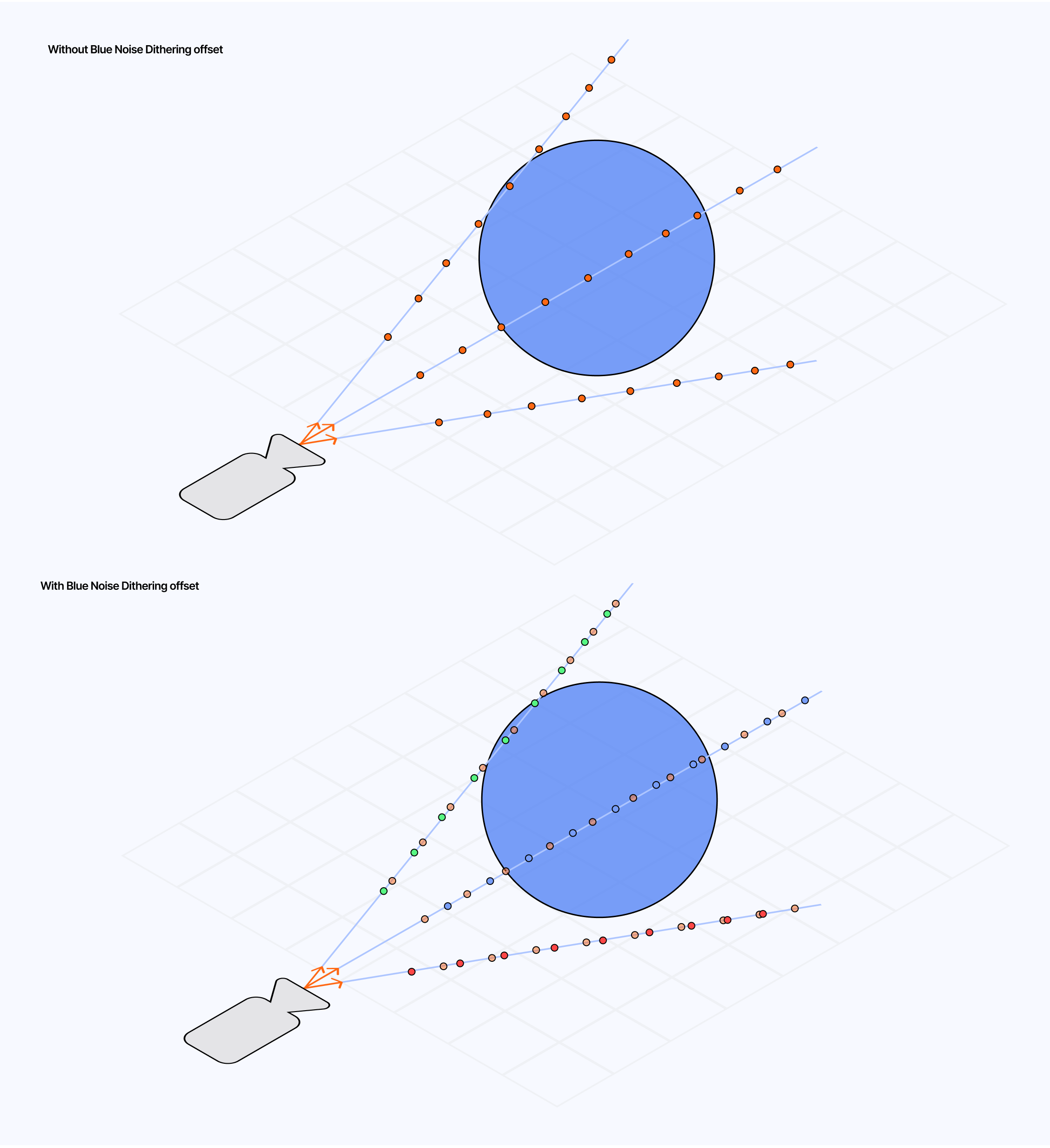
Moreover, by slightly shifting the noise pattern on every frame we can increase the quality of our output and make the dithering pattern from the noise almost unnoticeable.
Adding Blue Noise Dithering
1// ...2uniform sampler2D blueNoiseTexture;3uniform int frame;45//...6void mainImage(const in vec4 inputColor, const in vec2 uv, out vec4 outputColor) {7// ...8float blueNoise = texture2D(blueNoiseTexture, gl_FragCoord.xy / 1024.0).r;9float offset = fract(blueNoise + float(frame%32) / sqrt(0.5));10float t = STEP_SIZE * offset;1112for (int i = 0; i < NUM_STEPS; i++) {13vec3 samplePos = rayOrigin + rayDir * t;14// ...15}16// ...17}
The demo below implements this method. In it I:
- decreased
NUM_STEPSfrom250to50 - increased
STEP_SIZEfrom0.05to0.5
Thus going from 5000 iterations to 100 with a similar output quality.
With all the details of our volumetric lighting post-processing effect implemented, we can now focus on a few applications of this effect and observe how it can significantly alter the look and feel of a scene. You may have seen this effect featured in many video games or digital art pieces as a way to flood the scene with atmospheric light, filling the air with beams of light and shadows, thus making light more like an asset and not just "hitting surfaces".
In this section, I wanted to offer a breakdown of some of my creations that leverage volumetric lighting where it really shines (no pun intended) to bring that same bright atmospheric vibe onto my work.
Arches
I had this scene in my mind as a goal the very moment I started looking into this topic. I visualized this tall yet narrow series of arched doors where beams of light could shine through. The columns located between each door would cast striking shadows against the bright backdrop from the light on the other side.
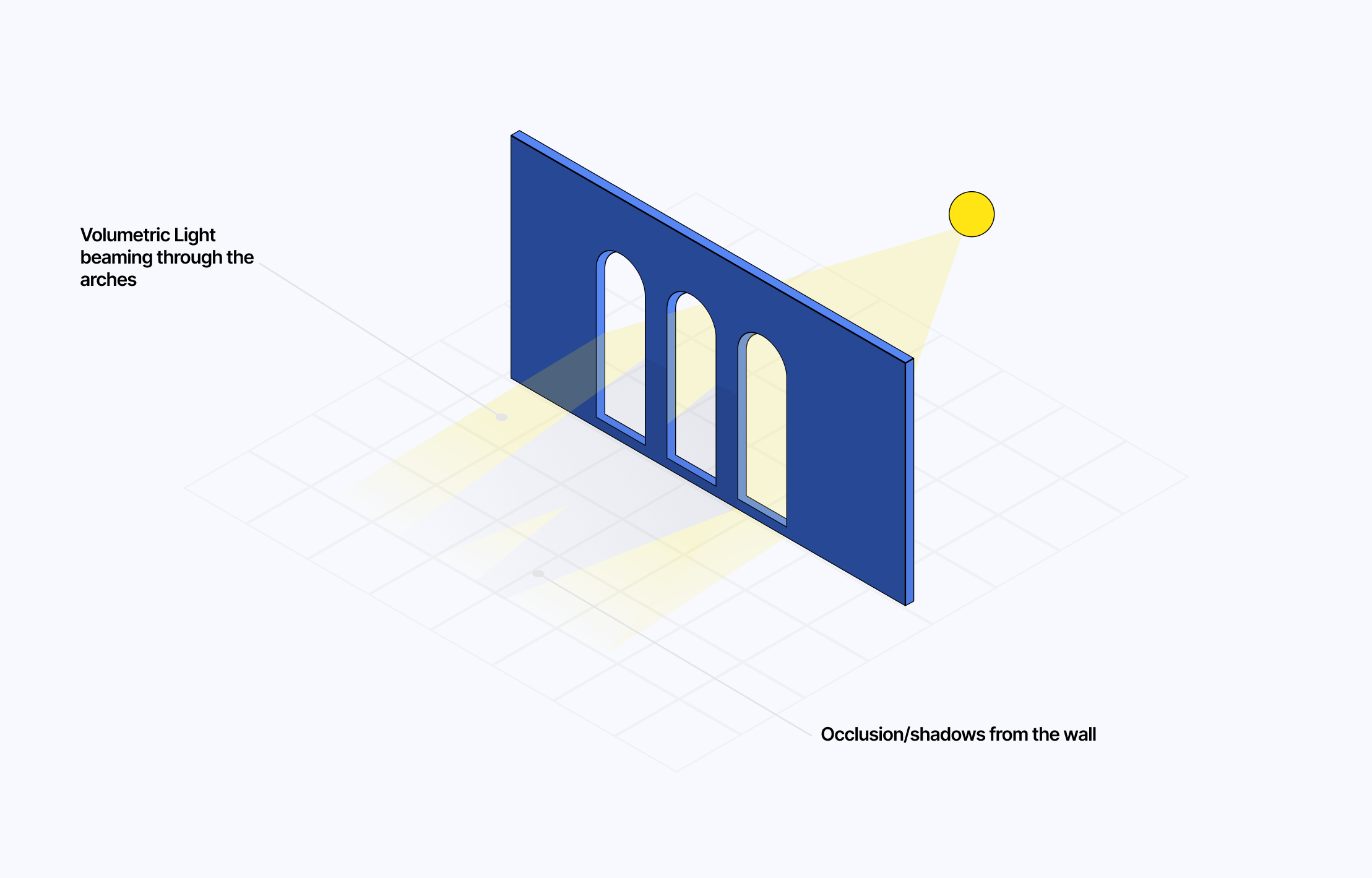
Luckily, the implementation of the effect allowed me to realize this vision:
- The volumetric raymarching aspect allows us to give our light the shape necessary to be visible through the air while shining through the door.
- The shadow map of the scene will ensure the beams of light are occluded where needed on the scene, especially when hitting the columns separating the different arches.
- The support for fog/clouds can give a mystical look and feel to the scene while emphasizing the light.
I got the idea of adding stairs to the scene from a similar project on Spline by Vlad Ponomarenko. These are simple CylinderGeometry stacked on top of one another with decreasing radius. I did not even bother making those instances as they are only a few steps (maybe I should have).
The demo below contains all those little details that make the scene beautiful yet so moody at the same time. It uses the same effect we built in this article and is a great way to see the difference volumetric lighting can make.
Asteroid Belt
I love a good space-themed 3D scene, and always need a good excuse to work on one. Here, it felt natural to explore how volumetric lighting could amplify the brightness of a sun or the darkness of planets eclipsing their star.
The principle behind this scene remains relatively simple:
- We have a central source of light: a star, which is a
sphereGeometryusing ameshBasicMaterial. I also positioned at the same coordinate apointLightso we would have light propagating and shadow cast in every direction.
1<mesh ref={lightRef}>2<pointLight castShadow intensity={500.5} />3<sphereGeometry args={[0.5, 32]} />4<meshBasicMaterial color={new THREE.Color('white').multiplyScalar(10)} />5</mesh>
- Two asteroid rings, each composed of their own set of
instancedMeshusing an asteroid geometry and a blackmeshStandardMaterial. This allowed me to scale up the number of objects in the scene without impacting performance. - Our volumetric lighting effect with a slightly tweaked behavior: the direction of the light will always point from the original position of the light towards us the viewer (camera position). This allowed me to only have light raymarched where relevant/visible, while also giving the impression to the viewer that it is shining in every direction.
- On top of that, the light camera will have a large fov of 90 degrees and will always point towards the main camera. Thus, no matter our point of view, we will have the widest possible shadow map of our scene and see beams of shadows from the volumetric light being occluded by the many asteroids in our scene.
1const lightDirection = new THREE.Vector3()2.subVectors(camera.position, lightPosition)3.normalize();45lightCamera.position.copy(lightPosition);6lightCamera.lookAt(camera.position);7lightCamera.updateMatrixWorld();8lightCamera.updateProjectionMatrix();
- I also tuned out any atmospheric effects for more realism, hence the
FOG_INTENSITYis turned down to0.02.
This, combined with a high-resolution shadow map, results in a beautiful space scene, leveraging volumetric lighting to make the light emitted from the star feel more bright and powerful.
You may notice the shadow beams flickering at first. This is a side-effect of the shadow map resolution. Try a higher resolution and observe how the effect becomes more stable. This type of artifact tends to happen in any scene featuring a large number of objects occluding the light, even with simple geometries. I had a similar issue when attempting to reproduce the gorgeous work of @5tr4n0 a digital artist leveraging volumetric lighting beautifully.


got tempted to rebuild this in webgl using my volumetric lighting shader work not as good but still a fun one to build https://t.co/c0Q8rL0GA0 https://t.co/PmkI0IKvku
On my end, I tend to settle for a shadow map of 512x512px to strike the right balance between performance and a minimum amount of shadow artifact.
With our effect fully implemented and operational on the few demo scenes we just went through you may be wondering: what's next?. The volumetric lighting post-processing shader we built bit-by-bit throughout this article may look relatively polished, there are still, however, a couple of pitfalls worth mentioning that we do not handle as of now:
- Throughout this article, we only ever considered one single source of light, the effect has no way to handle multiple sources at the moment.
- The shadows are only ever observable in the direction of the light. This is very apparent in the asteroid demo, and why I opted to have the
lightCameraalways pointing towards the camera to hide this limitation. But, what if we wanted a volumetric point light that could cast shadows in multiple directions?
This last section aims to answer those questions and provide a few examples I implemented to explore solutions. It also serves as the conclusion of our exploration of volumetric lighting.
To answer the first issue, scaling up to multiple light sources is not much trouble besides requiring a lot of extra code for each new source of light:
- new
lighCamera - new
shadowFBO - passing each texture, matrices, and other arguments to the effect
- calculating the shadows, light scattering, and light accumulation
Once done, the only thing to do is to combine the light accumulation of each light and we have our volumetric lighting with multiple light sources working. The demo below showcases a complete working example with two lights, which you will see, is quite a bit longer than any example we've seen so far:
Unfortunately, my solution to the second pitfall required quite a bit of refactoring, and the result is, at best, a cool hack.
We know that the process behind our shadow beams relies on a lightCamera pointing in a given direction. Its field of view is limited and thus, we can't capture the shadowMap of the entire scene. To do so, we would need a camera in every direction: top, bottom, left, right, front, back, and as many dedicated FBOs. That's a lot of code. Too much. Luckily for us, Three.js has a neat utility called a CubeCamera that bundles together six cameras and a WebGLCubeRenderTarget for us to store and read the resulting texture.
Setting up a CubeCamera and WebGLCubeRenderTarget
1const shadowCubeRenderTarget = useMemo(() => {2const rt = new THREE.WebGLCubeRenderTarget(SHADOW_MAP_SIZE, {3format: THREE.RGBAFormat,4type: THREE.FloatType,5generateMipmaps: false,6minFilter: THREE.LinearFilter,7magFilter: THREE.LinearFilter,8depthBuffer: true,9});10return rt;11}, []);1213const shadowCubeCamera = useMemo(() => {14const cam = new THREE.CubeCamera(15CUBE_CAMERA_NEAR,16CUBE_CAMERA_FAR,17shadowCubeRenderTarget18);19return cam;20}, [shadowCubeRenderTarget]);
However, there is an issue that was almost a blocker when I encountered it: there is no CubeDepthTexture. So I had to resolve myself to build my own "depth texture" by:
- Implementing a custom
shadowMaterialthat returns the normalized distance between any objects of the scene and a light position uniform. - Replacing the materials of all objects in the scene with the
shadowMaterial. - Take a snapshot of the scene with the cube camera.
- Restore the scene to its original state.
Using the shadowMaterial to extract depth data
1const shadowMaterial = useMemo(2() =>3new THREE.ShaderMaterial({4vertexShader: \`5varying vec3 vWorldPosition;6void main() {7vec4 worldPosition = modelMatrix * vec4(position, 1.0);8vWorldPosition = worldPosition.xyz;9gl_Position = projectionMatrix * viewMatrix * worldPosition;10}11\`,12fragmentShader: \`13uniform vec3 lightPosition;14uniform float shadowFar;15varying vec3 vWorldPosition;1617void main() {18// Calculate linear distance from the light source19float distance = length(vWorldPosition);20// Normalize distance to [0, 1] using the shadow camera's far plane21float normalizedDistance = clamp(distance / shadowFar, 0.0, 1.0);22// Store the normalized distance in the red channel.23gl_FragColor = vec4(normalizedDistance, 0.0, 0.0, 1.0);24}25\`,26side: THREE.DoubleSide,27uniforms: {28lightPosition: { value: new THREE.Vector3() },29shadowFar: { value: CUBE_CAMERA_FAR },30},31}),32[],33);
Then, we only need to pass the resulting shadowMapCube to our effect and its underlying fragment shader and modify our calculateShadow function to handle this new cube texture. After that, we have a volumetric lighting effect that can take into account objects in the entire scene in every direction and cast shadows accordingly. The next and final demo of this article contains my take on this issue. Again, consider this more a hack than a solution for production, as the result it yields is not as good as what we were able to accomplish together in other examples.
I hope you are as pleased as I am with how this topic and the demo scenes built using the new set of techniques turned out. Volumetric lighting felt like the perfect extension to my post-processing work while also expanding on some previous raymarching experiments, and that's why it felt natural for me to talk about it at this moment in time.
Using post-processing as a gateway to more physically accurate 3D work on top of stylization in future work will be an interesting undertaking. I'm also looking forward to diving into adjacent concepts such as global illumination or ambient occlusion, which are still nebulous to me, while also leveraging some of the new tools we learned about here like shadow mapping or virtual/cameras for other purposes. But, thanks to what I learned throughout writing this article, I feel confident I'll be soon able to get back to you with an article on those topics and ever more ambitious 3D work running in your browser to share with you.
Until then, I hope this article will be enough to keep you busy and inspire you to experiment more with volumetric lighting on your end!
You can learn more about Perspective Divide here. I also recommend checking out this video from Brandon Berisford who shares how to derive the Perspective Projection Matrix and details what this perspective divide step does.
There is also a
CONVOLUTIONeffect attribute which alongsideDEPTHgive you out-of-the-box special operations for your effect fragment shader. Refer to this documentation for more examples and information.You should definitely check out Inigo Quilez dictionary of SDF and try to have fun shaping your raymarched light with a couple of odd ones even though it would not be realistic.
In the case of caustics, we had to swap the material of the mesh with a
NormalMaterialto extract the normal data of the object and have it available as a texture.